Omnitech 1700 engine installation

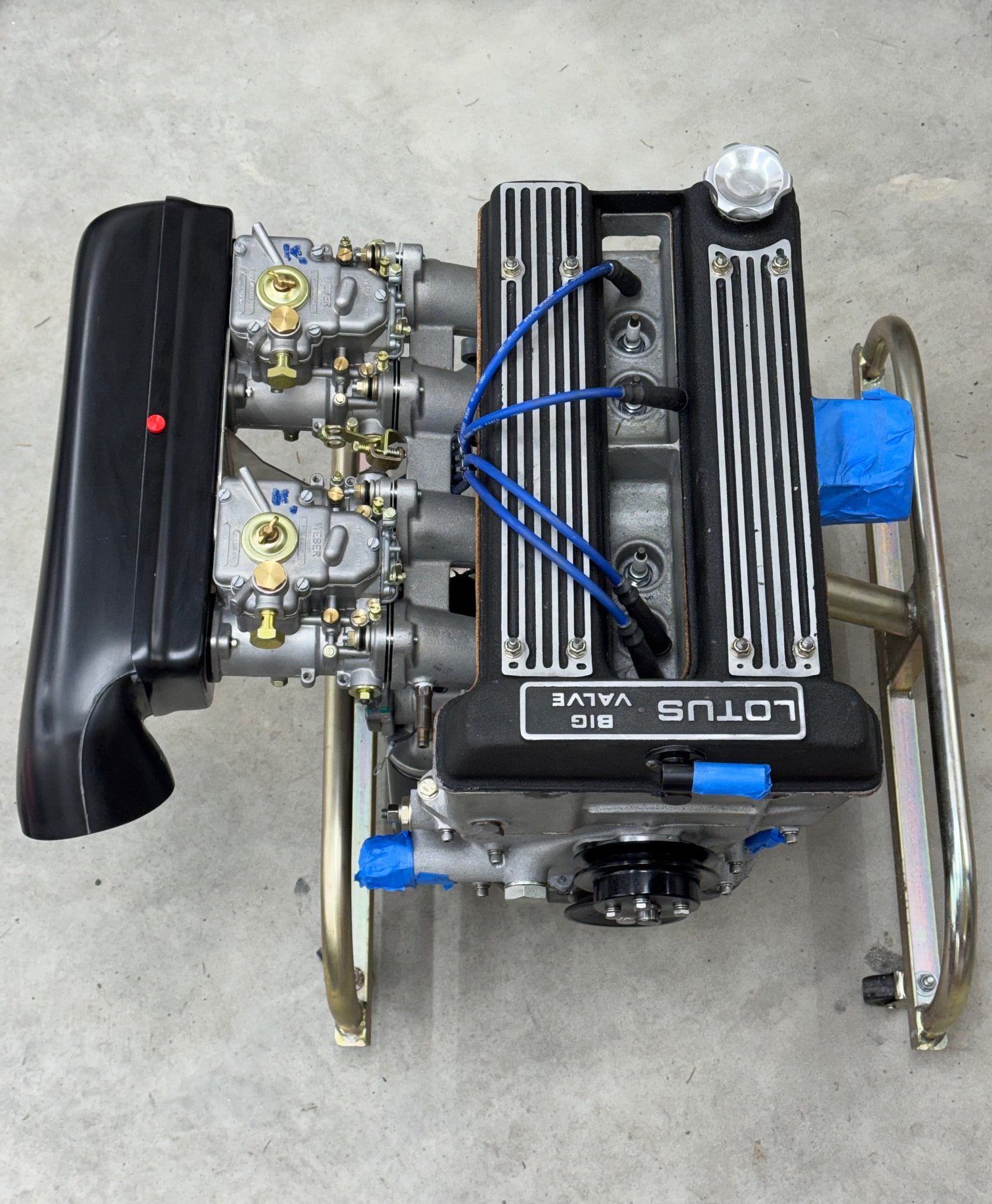
It’s finally time to start documenting my engine project. As some may recall from this thread, after discovering my engine had a warped head, three badly galled cam bearings, and four heavily scored cylinder bores, I picked up a recently completed Omnitech 1700cc with dyno hours.

My hope had been to complete the installation this month, but various issues ordering parts have put me far behind schedule. Between backorders and unexpected delays at some vendors, late February/early March now seems more realistic. However, I’m deep enough into this that I can start documenting my plan and progress to date.

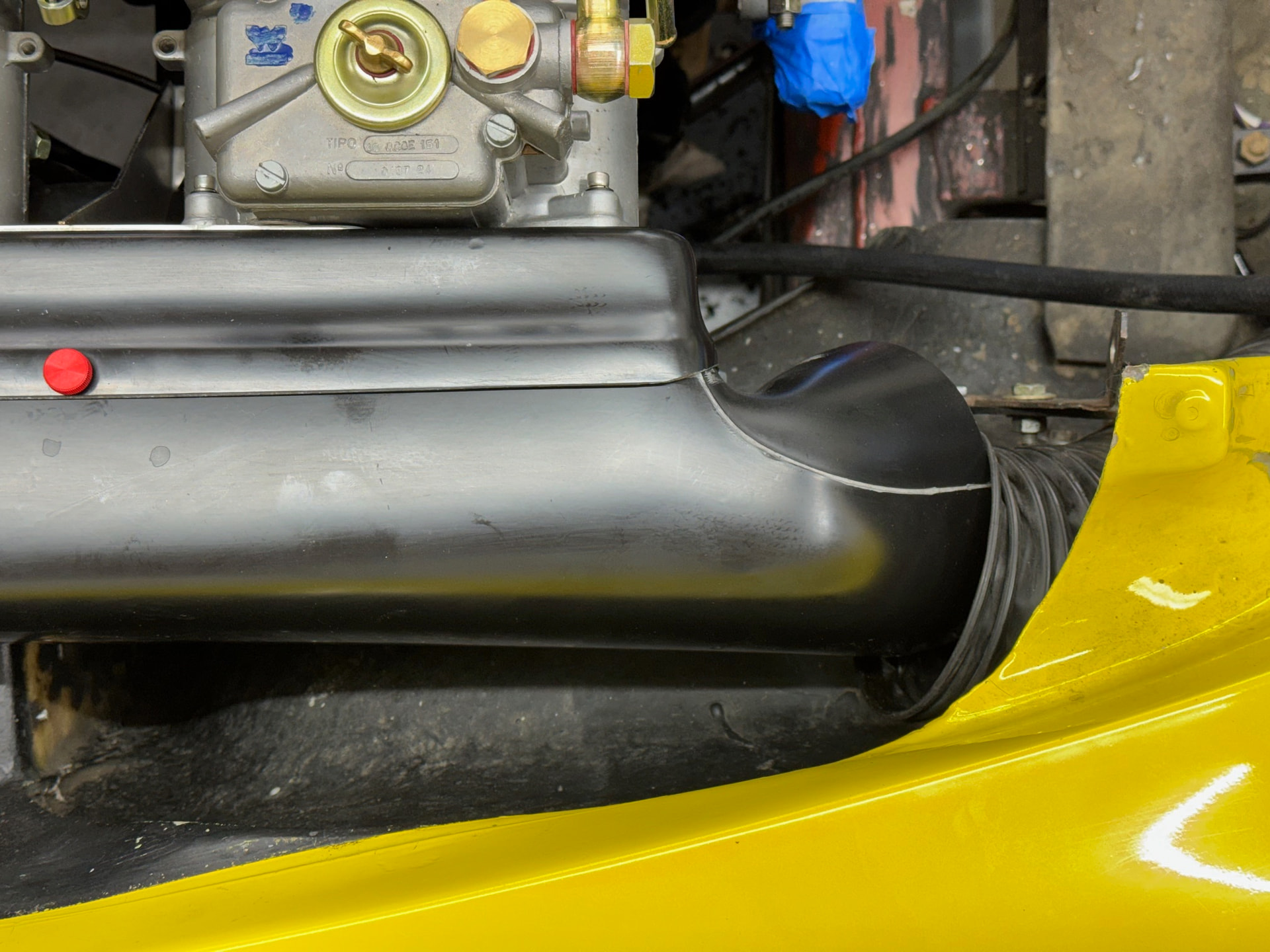
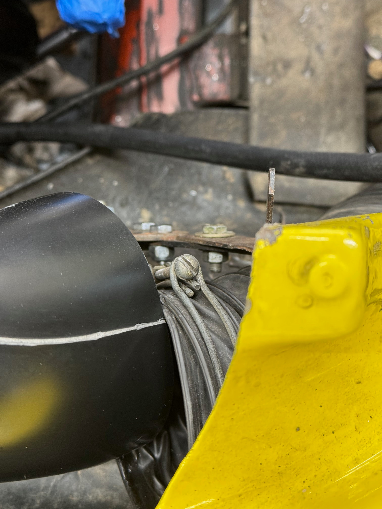
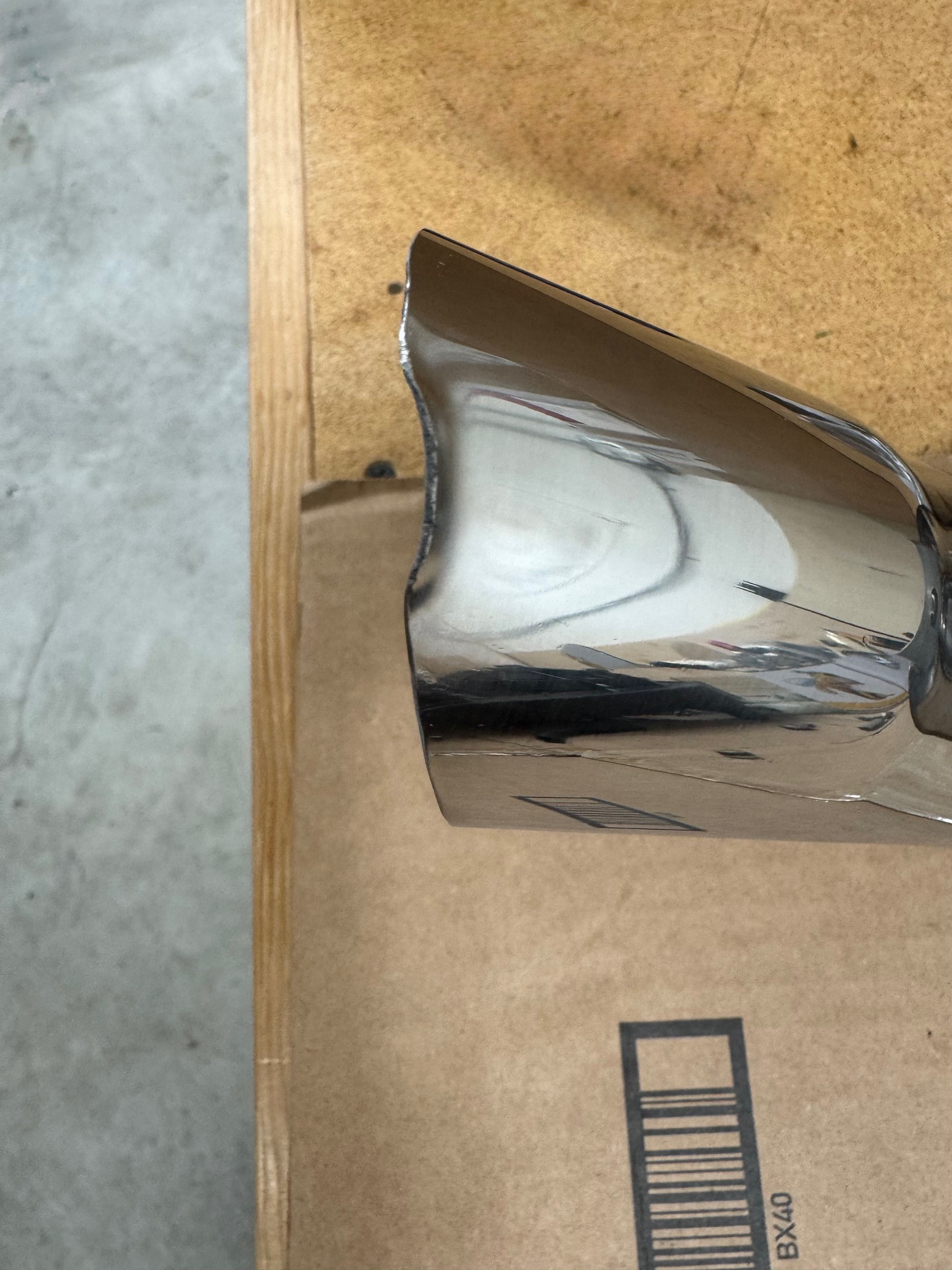
After a lot of internal deliberation, I’ve decided to use my existing RD Enterprises tubular header. I’m not a fan of their very short secondaries, and believe the TTR large bore header is a better match for the engine, but I already have the RD on hand and I know it fits. The TTR header may be a future upgrade. However, I did purchase their 2" exhaust for the remainder of the system. My existing exhaust has some problematic old repairs, making this an easier decision. Disappointingly, the muffler arrived with damage in a highly visible location at the top of the exhaust tip. Fortunately, RD was very responsive and has the replacement in transit. Kudos to Ray and George for making that process painless.

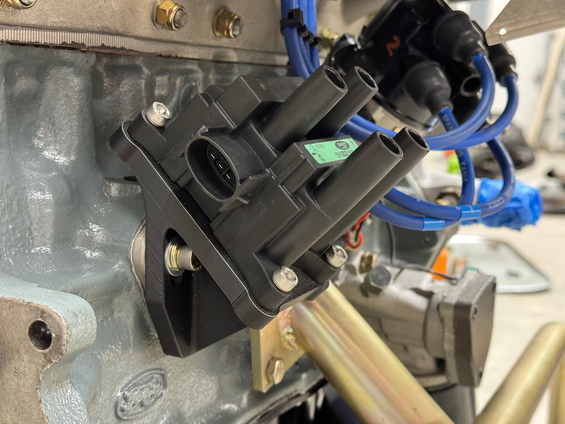
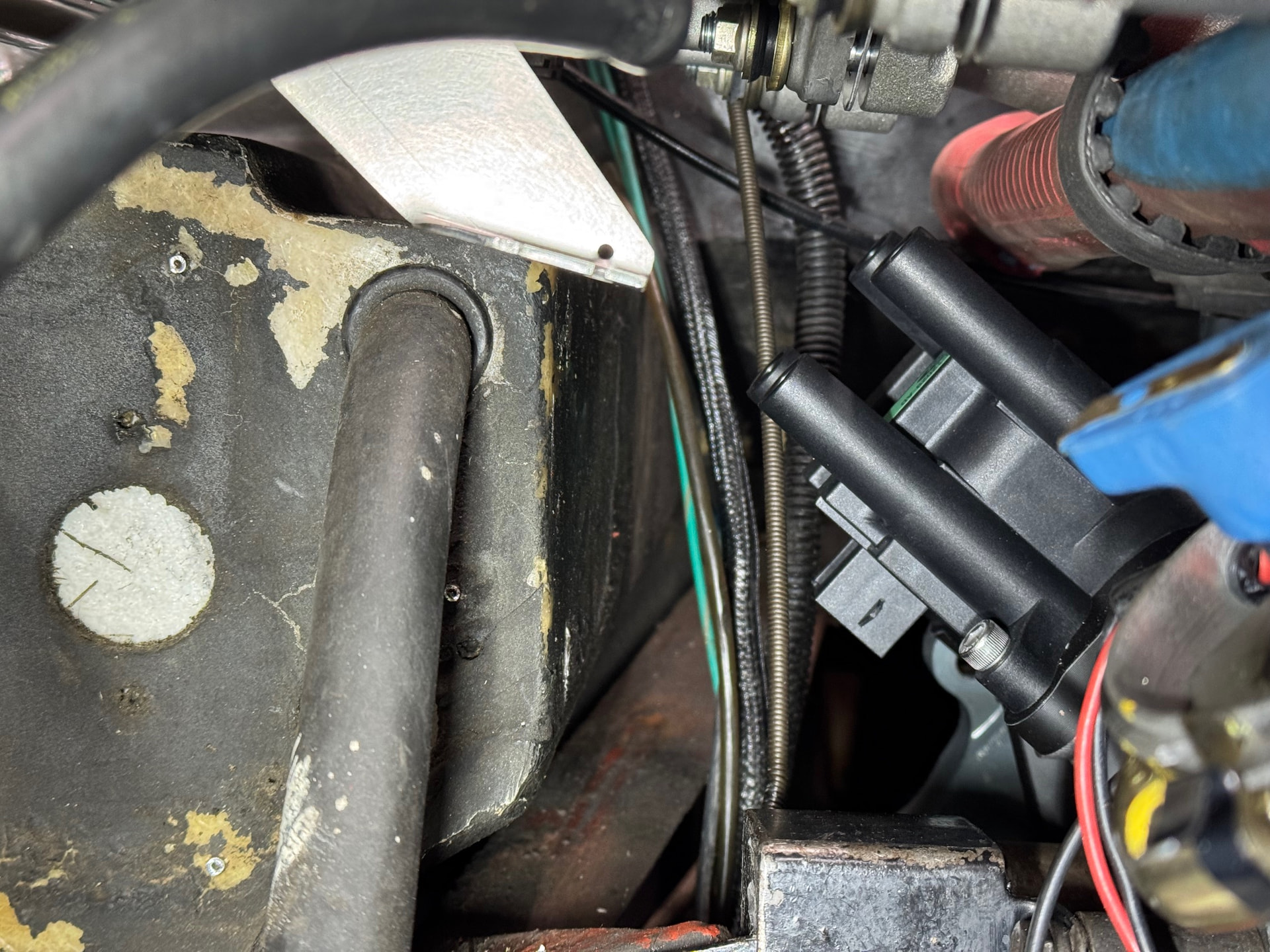
Next decision was ignition. Omnitech fitted a new points-based system as part of the build. My initial plan was to swap that out for the 123 Ignition from my old engine, then have the ignition curve mapped on the dyno and optimized for the engine and local fuel. However, I eventually convinced myself that it’s worth the trouble to install a 3D mappable ignition and have timing optimized for various throttle openings, not just full throttle. A Nodiz is on the way, but the other conversion parts are still stuck in ordering hell (QED won’t take payment and finalize the order until they determine shipping charges, which apparently takes a while.)

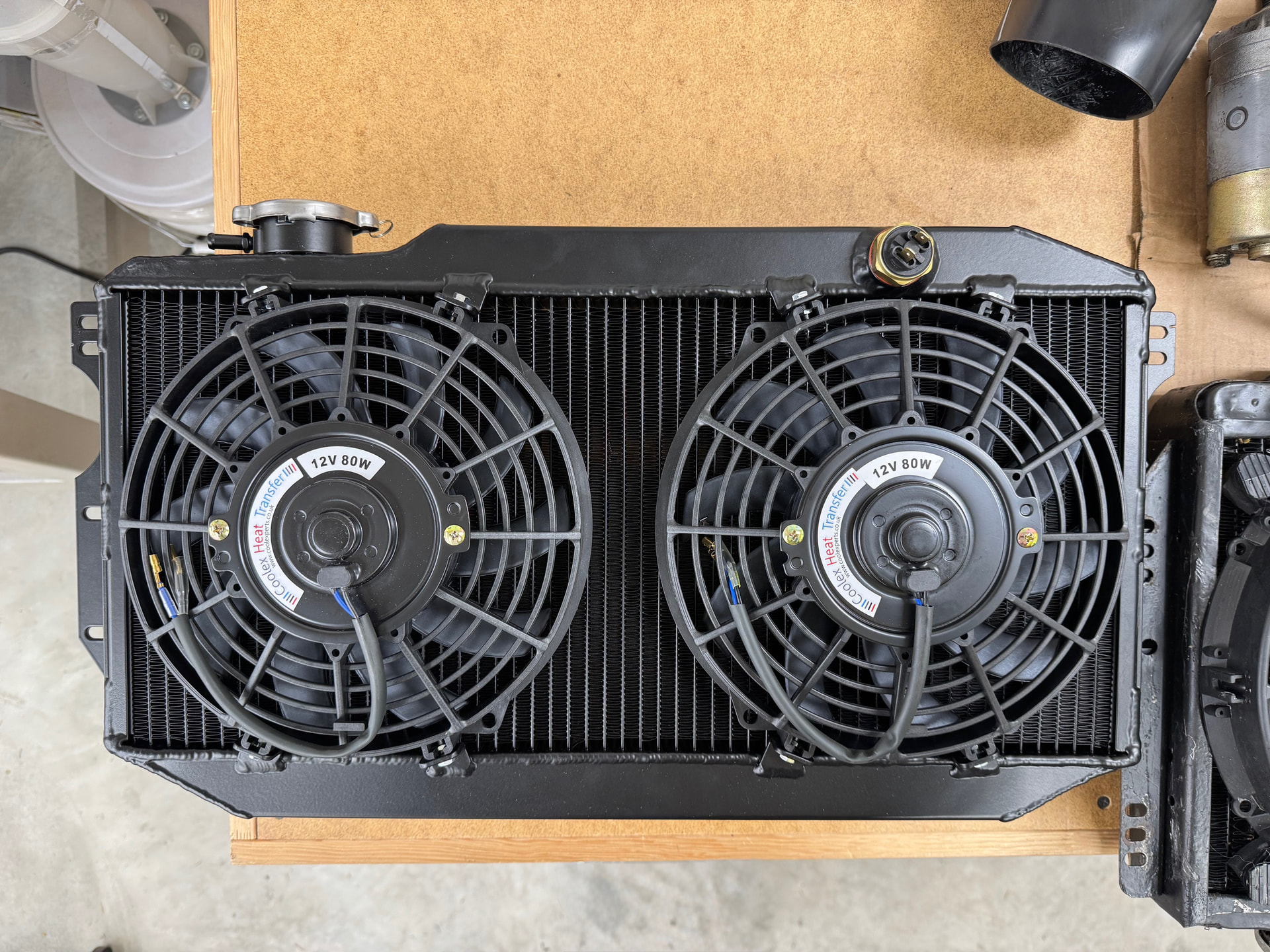
A twin fan Coolex radiator will handle cooling. I initially looked into having my S3 radiator recored and restored locally, but the price was effectively the same as the Coolex including shipping to the US. According to my scale, the Coolex with fans saves 7 lb (3.2 kg) over the S3 fitted with a different twin fan setup. That’s a nice savings at the front of the car.

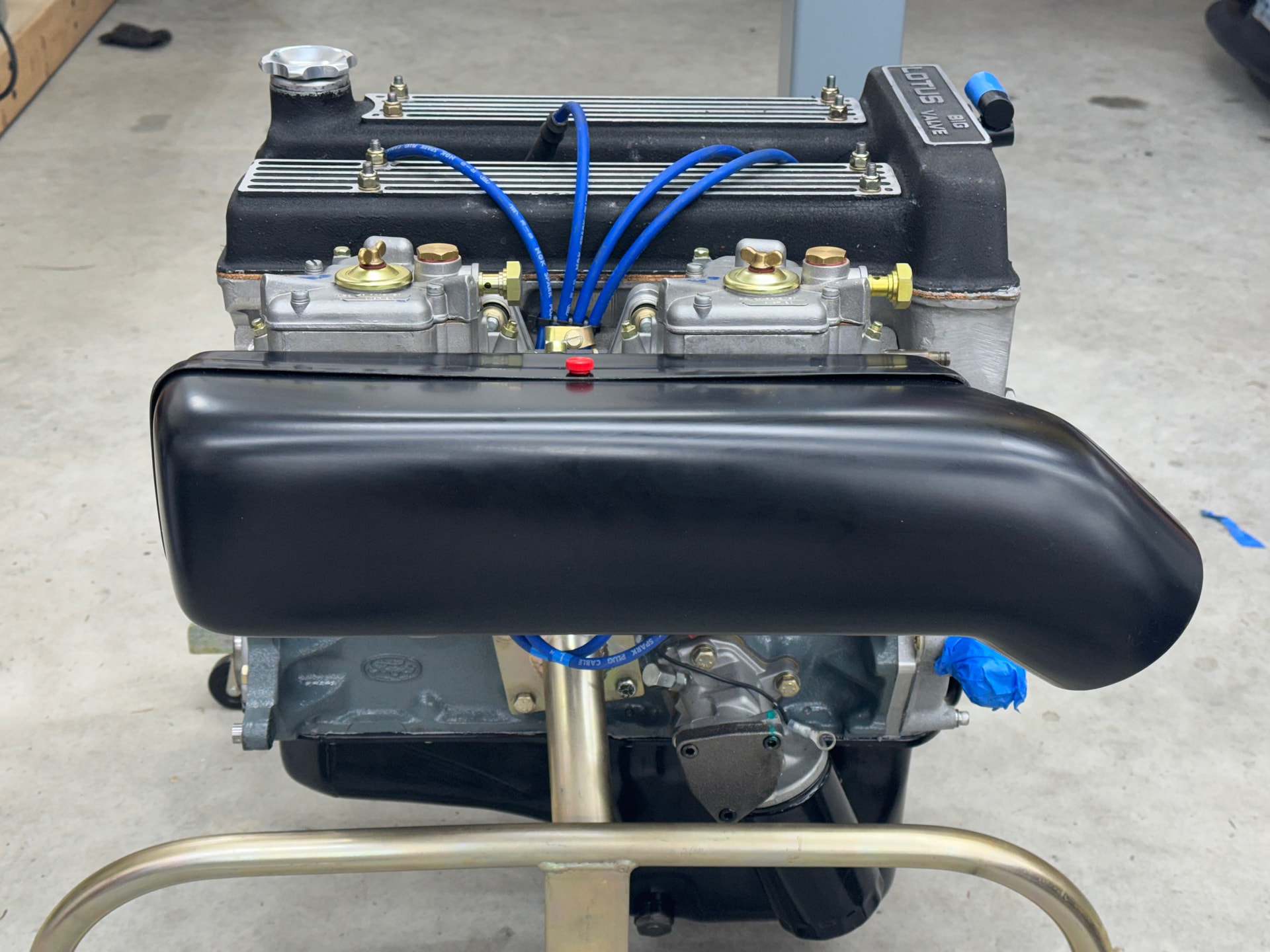
Since I’m changing from Strombergs to Webers, a new airbox was needed. I went with the air box from Famous Franks which has consistent depth from front to back.


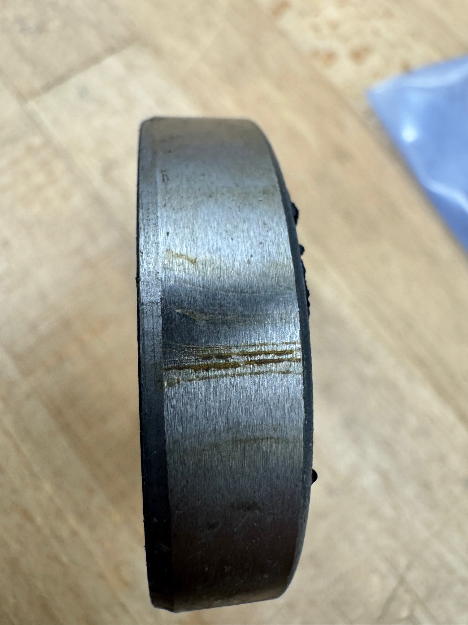
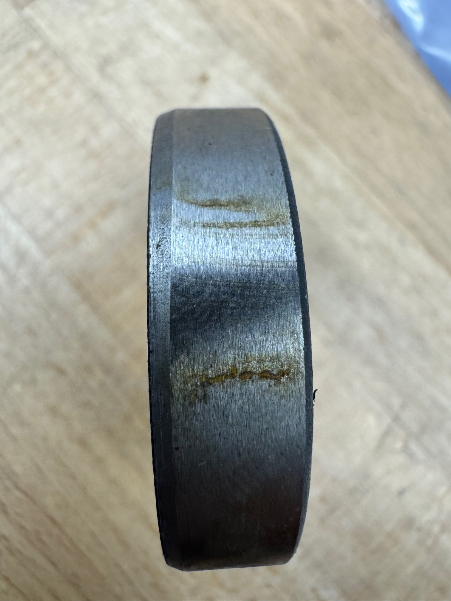
After speaking with a few people who have the Fidenza flywheel, I’ve opted to do the same and placed that order at the end of November. Unfortunately, that is one of the backordered items and is currently projected to ship at the end of January.

The last big item in the project plan is resealing the gearbox while it’s out. Hopefully I can start that within the next few days.

In the next post, I’ll cover progress to date.

-John

3 „Gefällt mir“

The first order of business was the fuel system. The engine arrived with the mechanical fuel pump removed and a block-off plate installed. This paved the way for an electric fuel pump conversion. The AAW harness I installed earlier includes wiring for a pump in the boot and an inertia switch under the bonnet, so this aspect of the job was already done. A Facet Gold Flo pump was installed in the well next to the fuel tank behind the right rear wheel, and a few custom hose brackets were 3D printed to keep things tidy. This was also a good time to update the plastic fuel line that runs from the tank to an ethanol resistant Cunifer hard line. After installation, pressure testing the system showed a steady 2.8-2.9 psi in the engine bay, which should eliminate the need for a pressure regulator. Of course, this assumes the gauge is accurate. Time will tell.


While I’m waiting for the 3D ignition parts to arrive, I spent time figuring out the mounting location for the coil. My objective is to keep it out of sight but reasonably accessible in case it needs to be replaced in the future. Some people have used the location vacated by the distributor, which I strongly considered, but while staring at the engine one morning, I realized the spot formerly occupied by the mechanical fuel pump would also work and it would be easier to fabricate a bracket for that location since it could attach using the blank-off plate bolts. It took a few prototypes to get everything to my liking, but I think it’s finalized. The pictures below are of the prototype, which will allow me to take measurements for the new plug wires. I’ll print the final version in an engineering filament that can handle the heat and is compatible with fuel and oil.


I should have everything I need to tackle the gearbox reseal by the end of the weekend and hope to start that project Monday or Tuesday.

-John

3 „Gefällt mir“

Who did you get the gaskets to reseal the gearbox from? I’ve been struggling with getting emails or phone calls returned for this same endeavor.

Nicely designed bracket. What filament are you using?

1 „Gefällt mir“

NIce! Looks to be an aftermarket fuel tank with a larger outlet. Who’s the maker?

The gaskets are from Dave Bean, and the aluminum fuel tank is from RD Enterprises. That job was done by the previous owner, so I don’t have any other details on it.

The bracket in the picture is printed with PLA just for prototyping purposes, but the final version will be PET-CF. I used PA-CF for the various parts printed for my Caterham (lots or customization on that car) which has held up well in areas of high heat under the bonnet. The PET-CF is rated even better in this regard and should hold up well in this location.

Some might question putting the coil under the carburetors. Many threads on here about moving it from the stock location for that reason.

The location doesn’t concern me. Happy to be corrected, but from my research, a distributor and a modern wasted‑spark coil pack operate very differently. The distributor has high‑voltage switching and arcing occurring beneath the cap. If there is a fuel leak and vapors accumulate near or around the cap—especially in the presence of cracks, carbon tracking, or poor sealing—then yes, there is a real risk of fire.

By contrast, a modern wasted‑spark coil pack, has no exposed internal arcing and is fully sealed with epoxy. There is no atmospheric spark source at the coil itself. While there is a theoretical risk from deteriorated spark plug wires, the Magnecor wires I plan to use are very high quality and will likely outlive me. So although the risk is not zero, it isn’t significant enough for me to pursue a more remote or visible location.

2 „Gefällt mir“

I was exploring mounting the coilpack on mine in the same location and had a different idea for the bracket, but not having access to a 3D printer, its much more crude… LMK if you want to print a few more for some $$…

Chalk me down as another one waiting for QED…

@2mAn I’m not comfortable selling something I haven’t fully tested. For all I know there could be an issue that will take a few hundred miles of heat and vibration to appear. I’ll send you a PM to discuss.

As for QED, my order took a phone call to sort, but I received word today it was sorted. Of course, no word on when it will ship.

1 „Gefällt mir“

I called QED right now to check on my own order and he said, “I hope to have it done before the end of the week” … I started my attempts to purchase in October :smiling_face_with_tear:

Indeed. The coil shouldn’t spark and should be fine under the carbs. The distributor unfortunately is designed to spark, and can’t be moved.

1 „Gefällt mir“

Fortunately, QED didn’t make me wait that long. It’s been 6 days since placing the order. This morning, I received a notice that my order has been processed. Not shipped. Just processed. In contrast, I ordered the TPS kit from Northampton Motorsports 7 days ago and it arrived today. Painless process, no phone calls required.

Nice, generally my experience with the UK places are just like that… quick order and turnaround.

Not sure why this one has been difficult

For a LHD car , mounting a coil pack on the vertical surface of the right hand side footwell is convenient . I’m also running crankfire so distributor is no longer a source of sparks -

1 „Gefällt mir“

Thanks @cabc26b. I hadn’t considered that location, but it does keep it out of sight, and access would be easier than under the carbs. I’ll look into that today.

On a related note, I visited a local Elan owner yesterday to check out his cars and discuss the project. He raised concerns about the space in my original mounting location, pointing out that the coil will sit very close to the side of the footbox. With my engine out of the car, I hadn’t realized space there was at such a premium.

Using photos and a reference point on the DCOEs for footbox orientation taken from his car, I realized back in the shop that clearance would indeed be tight. To gain about an inch of space, I printed a new test bracket that rotates the coil 90° and pulls it closer to the block. It should work, but after seeing your setup, perhaps I’m making this harder than I should?

When looking at the front of the footbox this morning, rather than fiberglass as shown in @cabc26b 's photo, there was a wavy, delaminating pressboard panel riveted in place. After removing what I suspected was a bodged repair (pressboard? in an engine bay? really?) I discovered this was in fact a Lotus part — complete with a stamped 26B part/ mold number on the back. What I didn’t realize is that holes for the master cylinders, steering shaft, and handbrake cable for both LHD and RHD cars were included in the molds rather than drilled later during body prep. The unused side was then covered with a panel. I’ve convinced myself that this is the best location for the coil, but to strengthen it, I’ll replace the pressboard with 1/16" thick aluminum.

I’ve been digging into the gearbox. Although the rear seal rubber was a little harder than the new one, everything else looked great and makes me think the gearbox was resealed fairly recently. However, it didn’t appear that sealant was used on the lower bellhousing bolt that threads into a through hole into the case. Perhaps this was the main source of the leak?

I did have a disappointing surprise when examining the new front seal. There are axial gouges deep enough to catch a nail and other areas of rust-stained pitting that also run front to back. This seal has clearly led a hard life in the parts room. I’ve requested a replacement.

1 „Gefällt mir“

I decided to test fit the engine this morning to check a few things, including footbox to coil pack clearance and ease of access when the coil is mounted to the block vs. the front of the footbox. With the updated block mount, there is about 1.5" between the side of the footbox and the nearest coil tower. Plenty when using 90 deg boots. It was also surprisingly easy to R&R with a long extension. After viewing things in place, I’m leaning towards using that location for no other reason than the front of the footbox could be used for an out-of-sight remote oil filter if I decide to do that in the future. McCoy installs a -10 AN nipple on the exhaust side of the block to accommodate this option and recommends it as he states it improves oiling to the rods. I’d prefer to avoid that extra plumbing, but I might change my mind down the road.


A disappointing ​discovery during the test install was airbox fit. The duct for the air hose has two issues: orientation and size. As shown in the pictures, it is angled too far towards the engine, placing the exit directly in front of the radiator bracket. It appears there “might” be just enough space to bend the hose behind the bracket provided the hose has enough flexibility. However, when attempting that, I discovered the size issue. There is no way the 3.5" hose will fit over the airbox intake. Because it’s a squished circular shape, I measured the circumference with a seamstress tape then calculated the corresponding circle diameter: 4.07". A 1/2" delta. Perhaps removing the wire coil over the last inch then warming the hose with a heat gun, would provide enough stretch to connect them. I can think of a few other ways to make things work, but before doing anything irreversible, I’ll check with the vendor to hear his thoughts.


3 „Gefällt mir“

I’ve got one of Johns engines as well. The professional that set the carbs spec’d 1.5-2lb and mandated a pressure regulator and gauge in the engine bay. I have a Plus 2 and I place the coil on the body below the carbs.

I have this added to this added to the list of things to confirm with John.

I mocked up an offset reducer for the airbox ducting that might be an easy fix. I’ll print it out of TPU and see how well it seals to the airbox.