Modernizing the wiring loom and other adventures

This will be a long, drawn-out, and probably drivel-filled thread that charts my journey to rewire a Federal-spec '68 S4 FHC and fix various other things-as-long-as-I’m-in-there. After receiving feedback from the group on my rewire options here, I chose to go modern using the Elan-specific harness from Advance Auto Wire (AAW). It’s not perfect, but on paper it seems reasonably close to what I want. They use modern, thin wall GXL wires, 7 relays, and 12 fuses, and provide excellent documentation. Presales support has also been first rate.

For me, the negatives are acceptable. Unless the harness is modified, connections to both the headlamp pod microswitches and the headlight flasher are lost. The other downside is the size of the fuse and relay holder, which they refer to as the Powerblock. At a beefy 7" x 7" x 2.5" (178mm x 178mm x 64mm) it’s appropriately named

Based on preliminary measurements, my initial thought is to create a new glovebox out of aluminum sheet and/or 3D printed parts that leaves room for the powerblock to mount beneath. For the wiring, the current plan is to replace all three looms, banish the bullet connectors, standardize on Deutsch Connectors, and where spades are required, use uninsulated terminals covered by either vinyl boots, or adhesive lined heat shrink. I’m also hoping to have the diligence to label each wire with adhesive Dymo labels protected by clear heat shrink tubing.

Lead time for the harness is 8-10 weeks, which is one reason this thread will be drawn out. In the post below, I’ll update what I’m doing while I wait.

-John

1 „Gefällt mir“

The first job was removing the dash, labeling the wires, and removing the dash loom.


Next was having the tach upgraded to work with the 123 Ignition. I’d previously installed a Spydia conversion kit, but it never worked well. Although needle bounce was improved, it was still present at higher rpm, and the accuracy was inconsistent. I was told I could optimize for accuracy either at the top of the rev range or the bottom. I couldn’t have both. As a result, the tach read about 2000rpm at idle. I sent the tach to West Valley Instruments in Los Angeles for an upgrade. Despite it arriving during the devastating fires, they turned it around in just two days. WVI was very easy to work with and the tach looks great; however, I won’t know for another few months if it works as hoped.

Next on the list is addressing the graying dash switches. I’ve read the various threads on restoration options and replacement switches. Since I was ordering a number of parts from RD Enterprises, I had them include a single replacement switch so I could see the quality first-hand. Unfortunately, the switch I received was very disappointing. As others have said, the edges are sharper than stock and the plastic is shiny and cheap looking. Additionally, my switch arrived with some damage and/or imperfections that didn’t give confidence that a set would meet expectations.


I’ve decided to start simple with a liquid refinishing product. Solution Finish has a good reputation on other forums and claims to remove the oxidation as part of its darkening process. Application is easy and the color looks good; however, it doesn’t hide the minor scratches that have accumulated over the past 57 years. Sanding first would likely address that, but part of me likes the history behind the wear. I may change my mind before reinstalling the dash in another 2-3 months. Unfortunately, I forgot to take a side-by-side photo of a refinished and untouched switch, but the photo below shows a refinished switch next to the new switch from RD, so you can compare to the shot above. In the flesh the switch does look much darker after applying the Solution Finish.


-John

1 „Gefällt mir“

Hi John! I can’t wait for the new forum software, hopefully it assists with ‘subscribing’ to threads. For now this will have to do.

1 „Gefällt mir“

Well, you didn’t have to wait too long :slight_smile:

3 „Gefällt mir“

It was a challenge I could not pass up!

2 „Gefällt mir“

Hi John,

Looking good! Spade terminals with heat shrink works nicely, a la a 1980s 911 (I recently replaced the fuse board on one, I see you have something similar if a bit newer in your garage?)

Managed to find a couple of in-progress photos from 2009 which show the concept if not the finished article.

Starting to lay it out:

I put two micro relays and the indicator flasher under/near the clocks and another four on the back of the glove box. The fuse board will be mounted so the fuses show on the inside of the glove compartment. At the time I was going to have an electric water pump controller inside the glove box but moved to a cartridge water pump instead when I rebuilt the engine a couple of years back. Hence the hole in the glove box.

This was a first test fit:

As I said in your other thread, it needs rework as plans have changed since then and there’s a few things that need to go.

Cheers,

Will

1 „Gefällt mir“

Thanks Will, I appreciate the photos. Your aluminium glovebox looks very nice!

With the loom removed, I was hoping to dry fit the dash and valance trim this weekend to start mapping out how much room there is to play with in the glovebox area before anything becomes visible to a seated passenger or driver. Unfortunately, I ran out of time. Hopefully next weekend.

I used adhesive heat shrink on spade terminals in the Caterham rewire but started thinking about the clear vinyl boots after seeing photos of the Autosparks looms. However, I’ll probably stick with what I know. Good eye on the 911. That’s a '95 993 C2 that I will have owned for 18 years next month. Hard to believe it’s been that long.

1 „Gefällt mir“

Sadly, not a lot of progress yet, but I do have a few updates. At the start of this project, I discovered the headlight pods no longer work. A little troubleshooting with a MityVac revealed the vacuum system was sound except for the headlamp pod switch in the dash. Using this excellent post as a guide, the switch was rebuilt and now the pods rise and hold with vacuum.

Another discovery is that the poorly installed carpeting isn’t simply a function of carelessness when putting the pieces in place. Some of the visible gaps are due to incorrectly cut pieces. Therefore, repositioning to close one gap, simply creates a new one at the other end of the piece. Also, the carpet quality isn’t great, and the fraying at some of the cuts is prolific. Digging deeper, the sound deadening on the tunnel appears original, but the floors have much thinner, cheap looking padding.


With the seats out, and a better view of what I’m dealing with, I’m finalizing my recarpeting plan. Currently I am leaning towards using this German Wool Square Weave. It’s nice quality and appears pretty close to the original loop carpet used in the S4, although I suspect it might be a little thinner. Given that will aid installation under door seals, I’m okay with that.

As for underlayment, rather than go with the original felt, I’m considering using this 1/2" thick product from DEI: Under Carpet Lite™ Sound Absorption & Insulation - 70" x 72" (35 sq. ft.) - Design Engineering, Inc It’s a similar style but given the focus on sound and heat management using modern materials, it might be a bit more effective. Weight seems consistent with the original felt at < 0.25 lbs per sq. ft. My next step is to remove all the existing carpet and padding in preparation for the recarpeting and to run the new loom to the back of the car.

By any chance has anyone used the carpet CAD drawing for the S4 FHC located here? S4 FHC Carpet Set Cad Drawings If so, was it accurate? I’m hoping to have this printed to scale to use as a template for cutting the new carpet.

Thanks,
John

1 „Gefällt mir“

For the switches. They’re easy to take apart, clean all the contacts and relubricate. You can paint the plastic switch bits with Plasticote, it works really well. I’m sure there is a US equivalent.

1 „Gefällt mir“

Thanks, I’ll probably disassemble and clean the switches, but I’m leaning towards keeping the rockers as-is. The scratches are more prominent in the photos than they are to the naked eye, and I kind of like a little patina. Given how long it will be before the rewiring is finished, I have plenty of time to pivot if I change my mind,

I decided to clean and lube the switches today. Some were in better shape than others, but they all needed a good cleaning and some grease. Below are pictures of a disassembled window switch. The first photo shows the interior with the rocker removed and the movable contacts still in place. Photo 2 has the movable contacts removed to provide a view of the fixed contacts, and photo 3 shows the underside of the movable contacts. In photos 2 & 3, only one side is cleaned to provide a before and after comparison.

2 „Gefällt mir“

The AAW wiring harness arrived Friday. While I’ve been waiting, I made a little more progress on other aspects of this slippery slope. The car’s interior is now stripped, the nasty looking seat brackets have been refurbished, I’ve upgraded all the dash lights to LEDs, and replaced the center console with one that is much higher quality.

I’m also rethinking my plans to use the German Wool Square Weave carpet. Short version is that given the cost of that material (about 4 times the cost of the carpet used in pre-cut kits), I either need to outsource it or take a big risk that I won’t screw it up and create an expensive pile of scraps; I simply don’t have confidence that I possess the necessary patience to create accurate patterns and cut the carpet correctly to size. At this point I’m leaning towards the kit from Sue Miller but that process has been very slow and is still not resolved. Stay tuned.

The word overkill comes to mind when looking at the new wiring harness. Most of the wires are 12-14 gauge, with some as large as 10 gauge and a few as “small” as 16 gauge. All in, but before cutting wires to length, the harness weighs over 15 lb (nearly 7 kg). With it in hand, I was finally able to begin work on determining the mounting location. The fuse box consists of four modules that screw to a thick plastic sheet, which AAW calls the Powerblock. The good news is this attachment method means the modules can be detached to aid mounting flexibility. The bad news is that wire length between them limits how much redistribution is possible. Although replacing overly short wires with longer ones would resolve that, I’d prefer to keep the original wiring intact.


First step was doing a rough CAD model of the original glovebox (actually a replacement from RD Ent) but with the back remaining flat for its length rather than angling forward at the midway point. An opening was added at the back for the fuses to poke through. Given this model exceeds the size of my print bed, it’s printed in three pieces that are taped together to enable a test fit. Fit was nearly perfect.

Next was removing the powerblock components and carefully unlacing all the wires to give me a better idea of how much flexibility there is without replacing any connecting wires. The short answer is not too much. There is, however, the option to disconnect the relay bases from each other and move them around and change their orientation.

With that approach, I think I see a way a couple of ways of doing this. Both involve a firewall mounted bracket that faces all the fuses and relays in the same direction rather than orthogonal to one another as with the powerblock. Option one faces them forward, with the fuses and three relay grouping (7-9) accessed via a door in the back of the glovebox, and the six relay block (1-6) immediately underneath the glove box. Option two faces them downward and likely requires reducing the depth of the glove box by about an inch or creating a step in the back where only the bottom half is shortened that amount. It has the added downside of requiring me to lay on my back to access fuses and relays in the future and will require a little more robust design to withstand the force from removing a relay. I’ve already printed a rough test bracket that allows me to check space for either option.

I’ll play around with this a little more this week, then print a protype to which I’ll attach the powerblock components and finalize the design. Once that’s done, I can proceed with the wiring part of the project. At this rate, completion ETA is sometime in 2026. :frowning:

3 „Gefällt mir“

The redesigned powerblock is done. I decided to mount the relays and fuses facing forward, and will make a new glovebox a bit shorter with a back door to access the fuses and three of the relays. The remaining six relays will be located immediately below the glovebox. The photos below show: the bare mount with spacers to account for the inner profile of the firewall; the mount temporarily installed behind the white glovebox shell I printed previously but with the back removed: and the portion that will hold the six relays peeking out below the glovebox.


The powerblock mounts to the firewall via three bolts. Because two of those bolts go through an area that isn’t flat, two spacers were designed which match the contours of the engine side and spread the load across a larger area of fiberglass. All parts were printed with PET-CF filament which is quite strong and can withstand very high heat without deformation.


And here is the mount with the various parts attached but without the relays installed. Next step is to actually start the rewiring.

5 „Gefällt mir“

I’ve not kept this thread up to date as planned. I wish I was writing it is done, but it feels like I’m closer to the beginning of the project than to the end. To avoid creating one really long catch-up post that no one wants to read, I’ll break it into a couple shorter, high-level posts that someone may feel like skimming when boredom hits them hard.

In this post, I’ll focus on the current status. Between parts delays, ordering the wrong parts, lack of time, and bouts of frustration, not a lot of progress has been made. As shown below, the car’s original wiring has now been labeled and removed. The replacement harness is largely in place. Largely, because I need some additional wire to finish the car. Aside from ground wires, I’ve terminated most of the wires in the boot and under bonnet. The exceptions are either due to lack of sufficient wire or wires that require large connectors (e.g. headlights) that will make it hard to remove if I decide to tape the engine bay loom rather than use split loom.

All the rocker switches were rebuilt and tested, and aside from the aforementioned missing wires, the back of the dash is done. I plan to use Deutsch connectors to make future dash removal easier. The bulk of the wiring will go through either one or two large connectors on the right side of the dash near the grounding point, while the items on the left of the steering wheel (LHD) such as warning lights, and turn signal wires to hazard switch, will go through a dedicated Deutsch connector on that side. I am waiting until the rest of the wire arrives and I do the final test fit of the dash before cutting the wires and terminating them with the required pins.

All wires are being labeled with special heat shrink tubing that works with an Epson label maker.

Mistakes to date have been surprisingly minor — although there is still time for a few major screw ups. A couple of wires were cut too short, I terminated two of the wires feeding one headlamp before running the wire through the grommet at the back of the headlamp pod, I reassembled the headlamp rocker switch slightly incorrectly, resulting in a testing failure and having to tackle that again, and I accidentally knocked a headlamp off the lift, shattering it into many little pieces.

Next post is about the challenges to date.

3 „Gefällt mir“

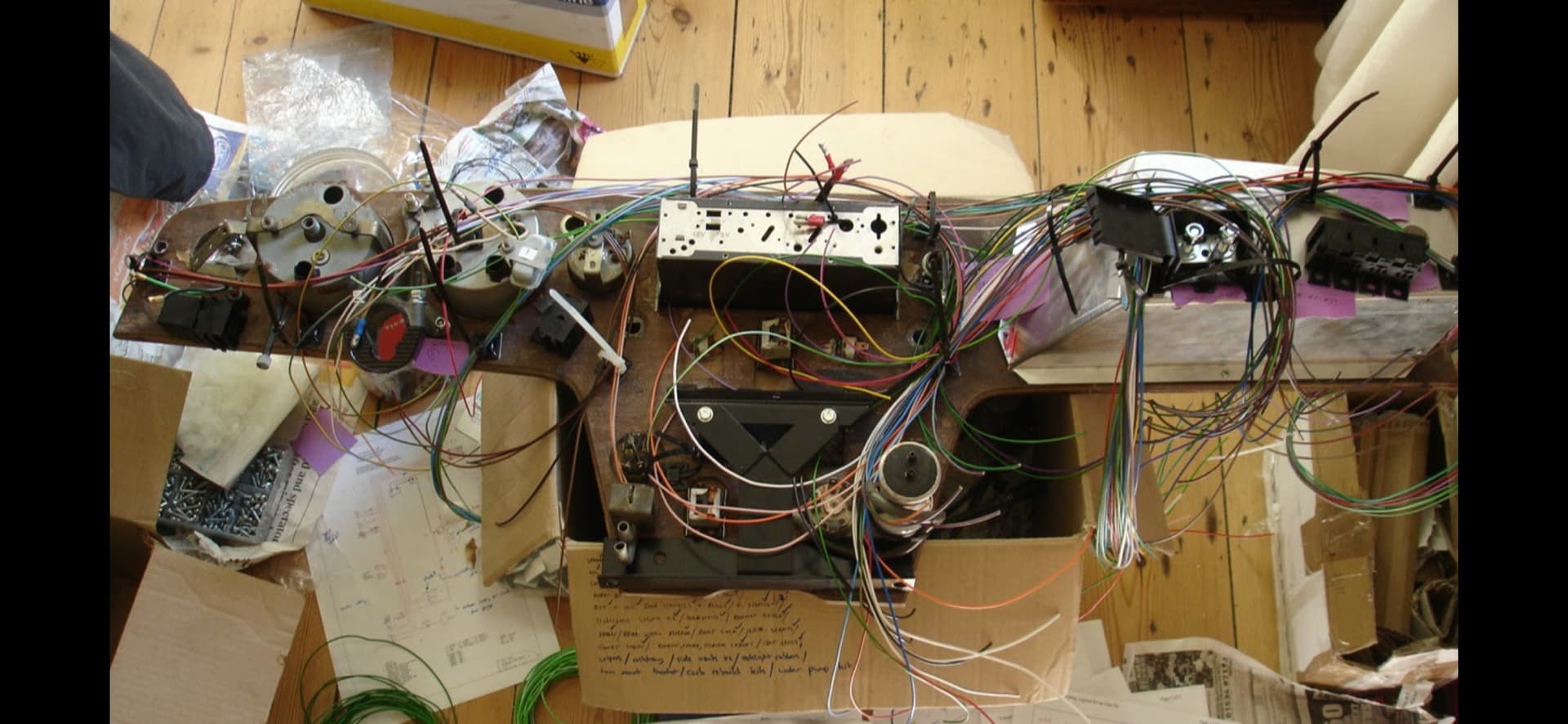
I’ll bucket this into challenges adapting the AAW harness to my car, and things on the car I discovered had failed/were failing.

Wiring
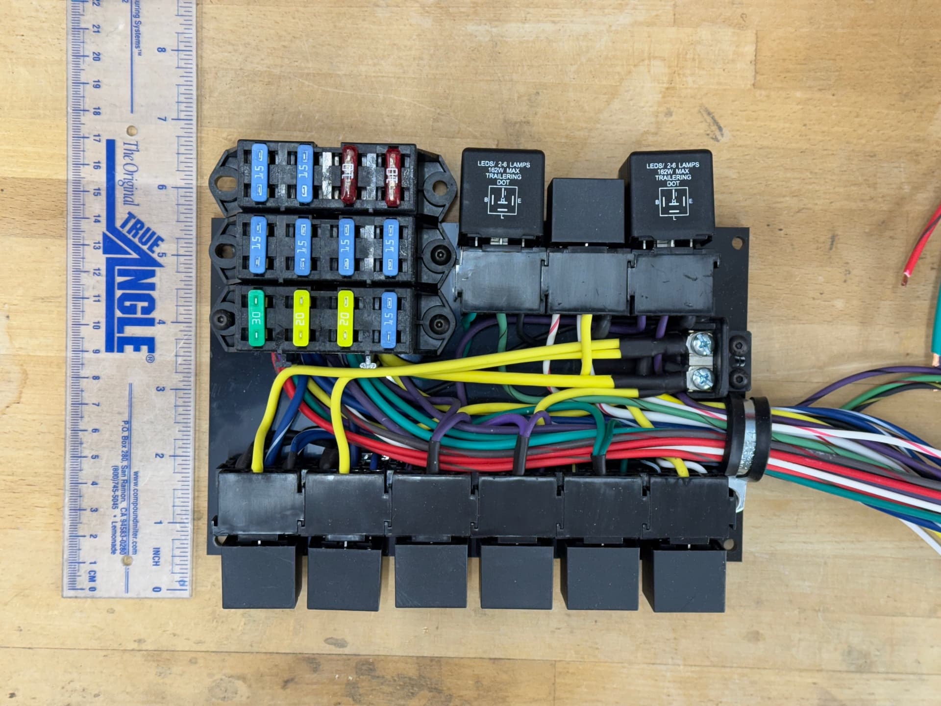
First issue was the indicator warning light on the dash. The AAW schematic shows there are dedicated wires from both the signal and hazard relays. Except there aren’t. It tuns out the wiring diagram shows the old relays, not the newer LED enabled relays. Some digging on the forum suggested wiring an incandescent bulb between the left and right signal wires leading from the hazard switch would work on both circuits. Something Steve at AAW later confirmed.

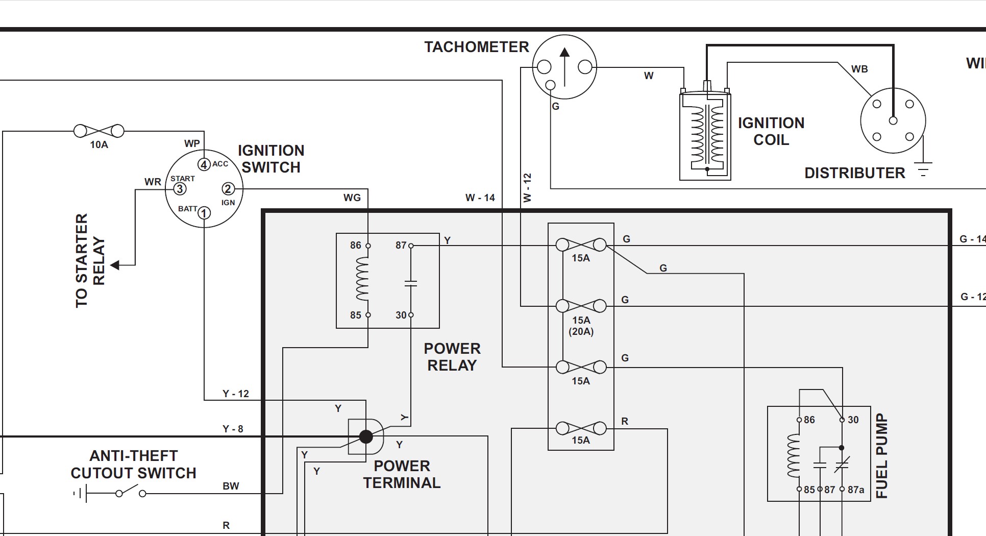
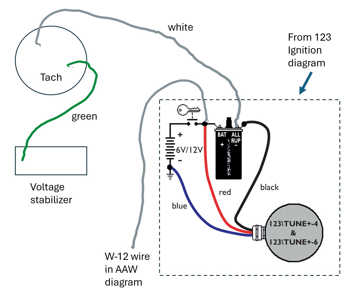
Next was the tach. AAW shows a green wire from the voltage stabilizer to the back of the tach a 12 awg white wire from a switched fuse to the tach, and a white 14 awg from the tach to the coil. My tach has been converted to RVC and has a single white wire coming out of the back, and a spade for the green wire from the voltage stabilizer. Adding to the complexity, my engine is using a 123 Ignition. The pictures below show the AAW diagram, and the wiring diagram from 123 Ignition with my planned integration with the AAW harness. If anyone sees an issue, please speak up.


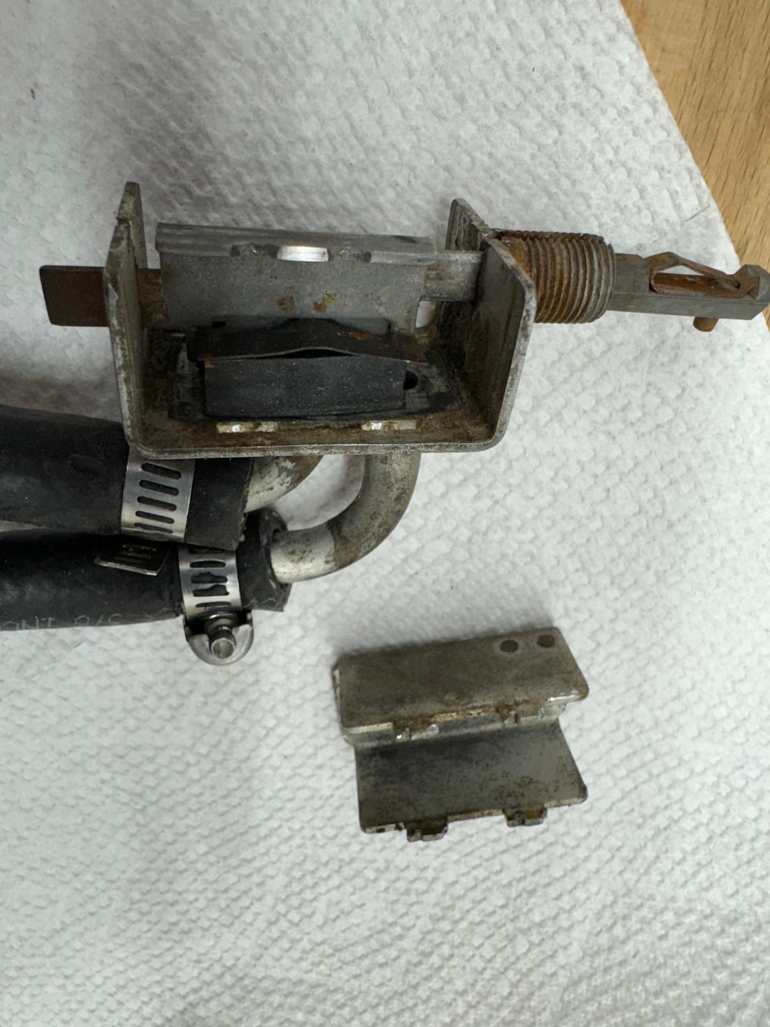
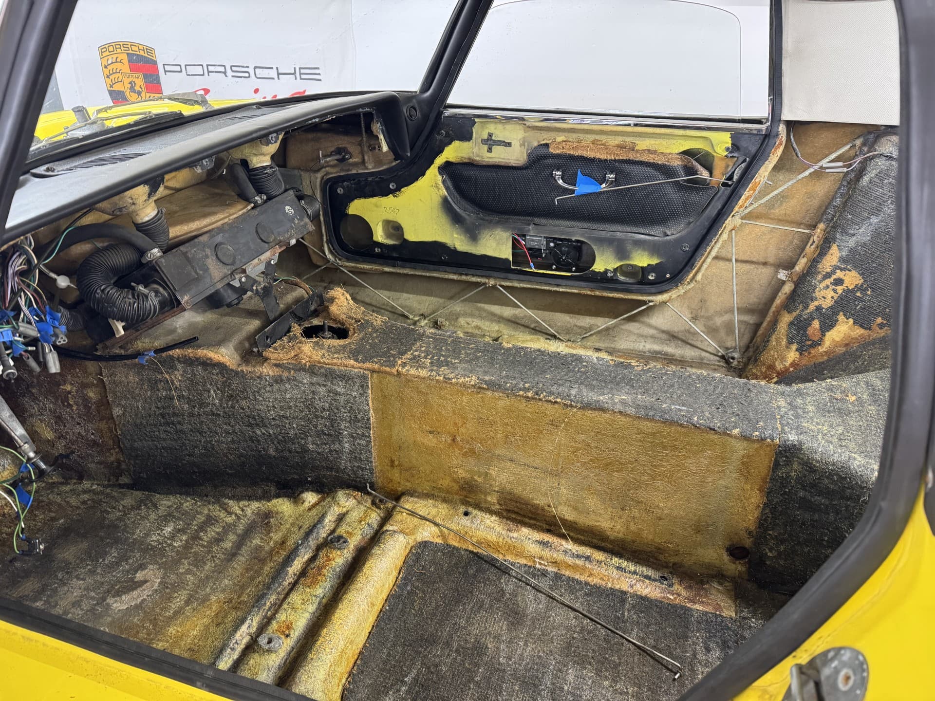
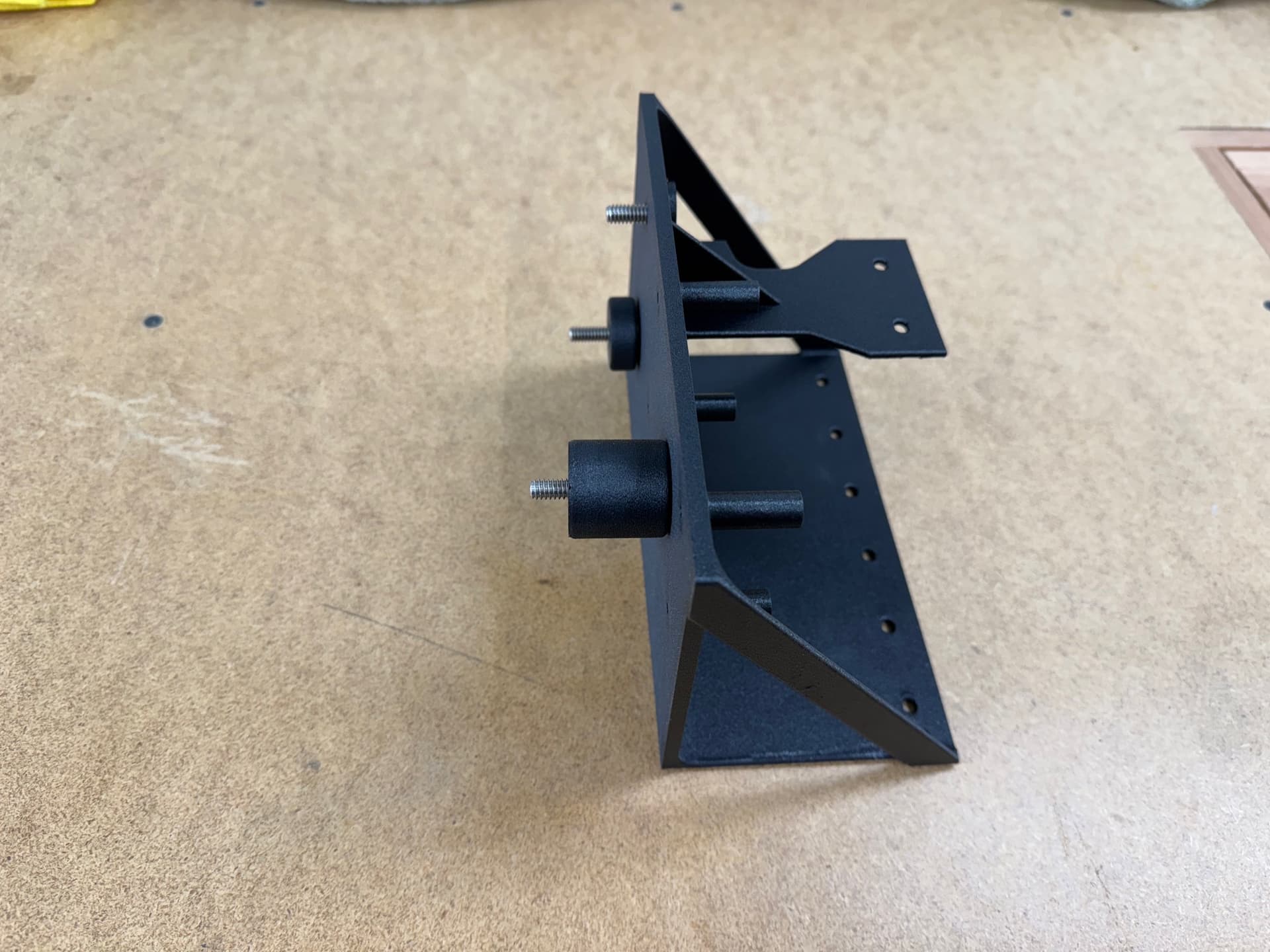
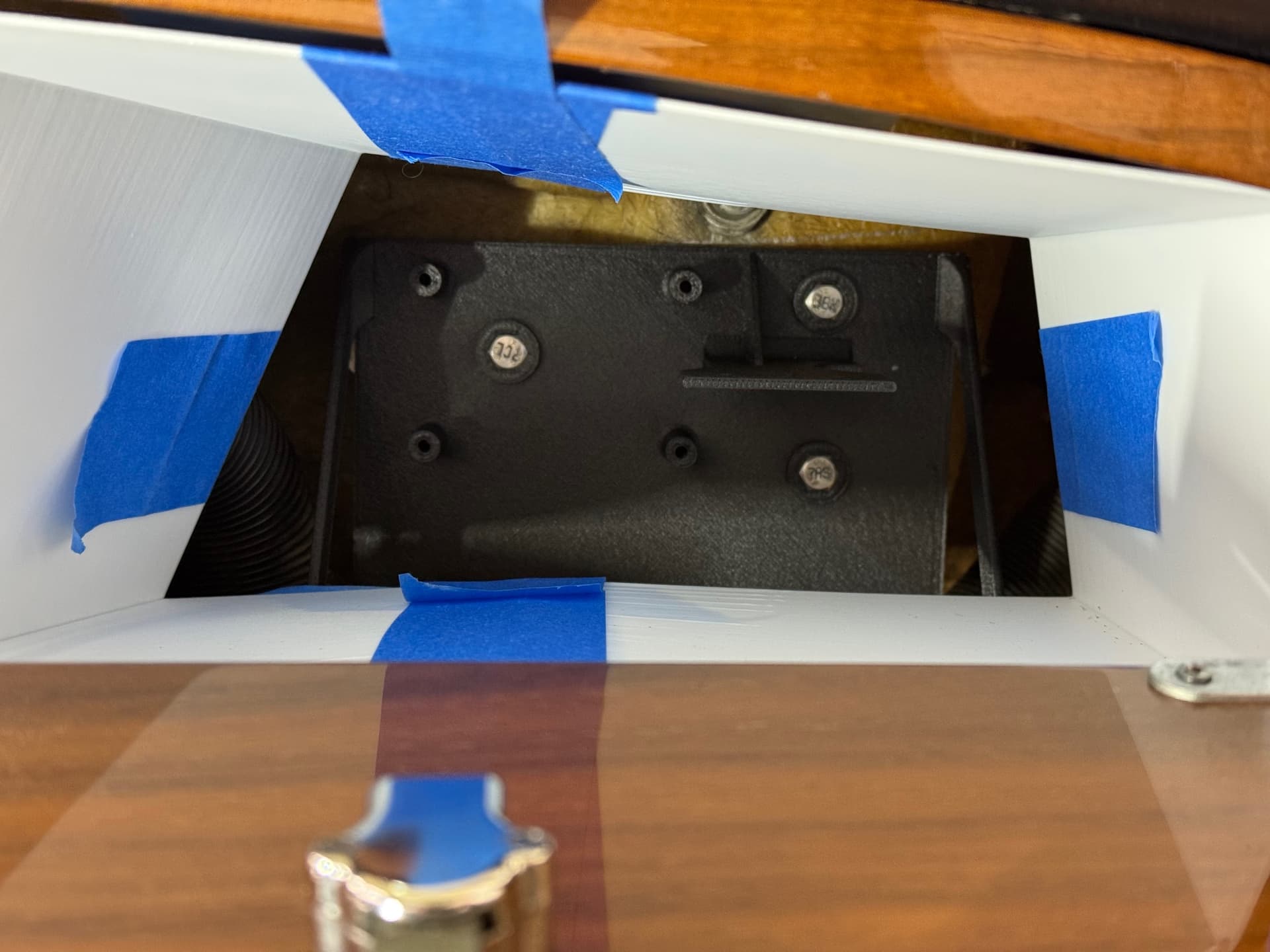
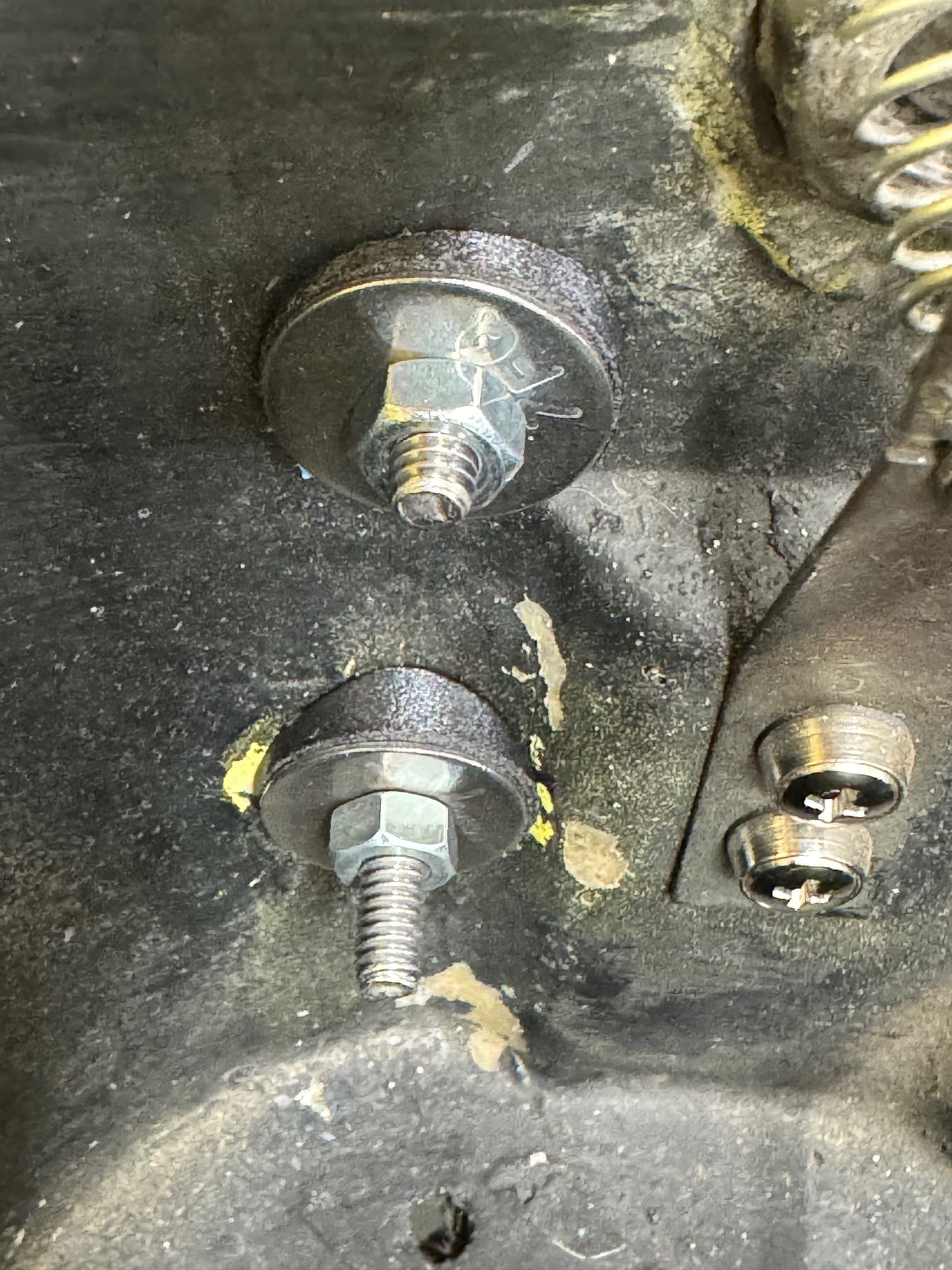
The other difference was the cooling fan. AAW has it setup to use a coolant fan switch and provision for an override switch in the cabin. However, my car is fitted with an adjustable fan controller with its own relay, and is wired differently. For example, its override switch connects to 12v+ whereas the AAW override switch connects to ground. I was unable to find a variable speed controller that didn’t have a native relay, which meant choosing between the controller or the AAW setup. I’m not crazy about how the controller was previously installed. They drilled and tapped a hole in the thermostat cover and applied a boatload of sealant (removed switch next to threaded hole shown below). It’s never leaked, but it’s not done to the standard I’d like to keep for the car. For now, I’ve decided to keep the controller as-is and cleaned up some of the wiring but also run the AAW wires into the correct locations in case I change my mind in the future. I suspect I’ll stick with the controller but eventually replace the thermostat cover with one designed to be fitted with a coolant switch/sensor.

Parts issues
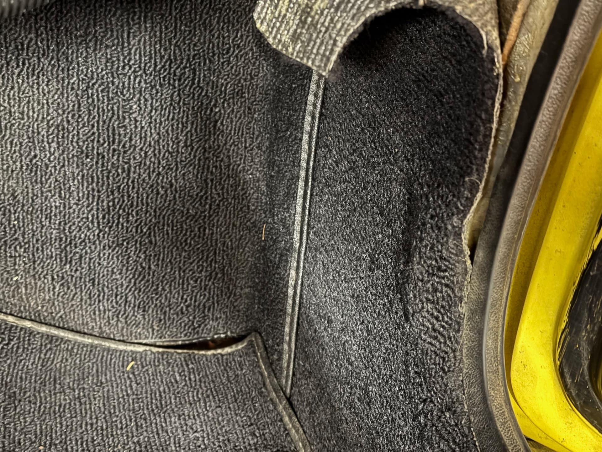
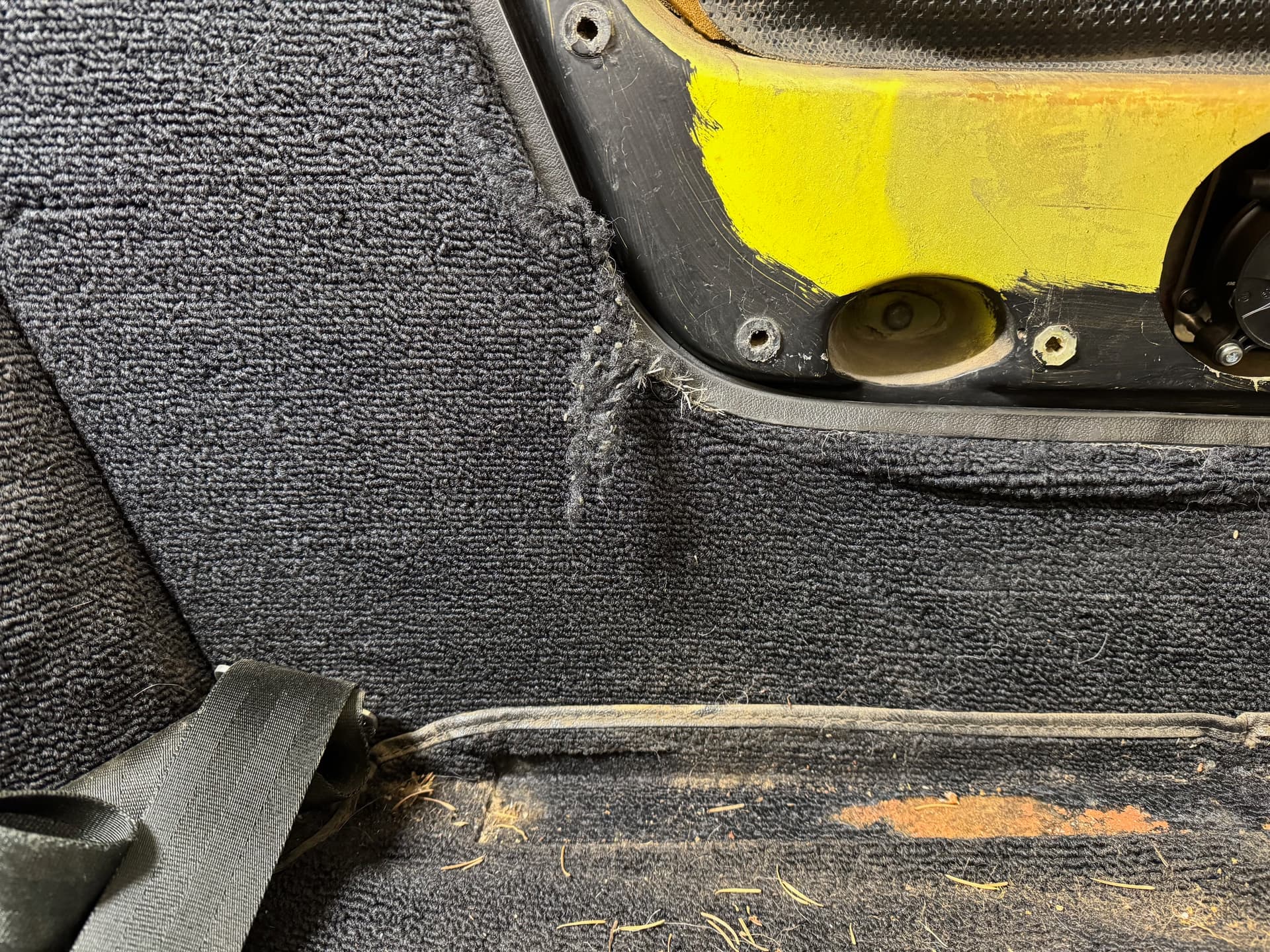
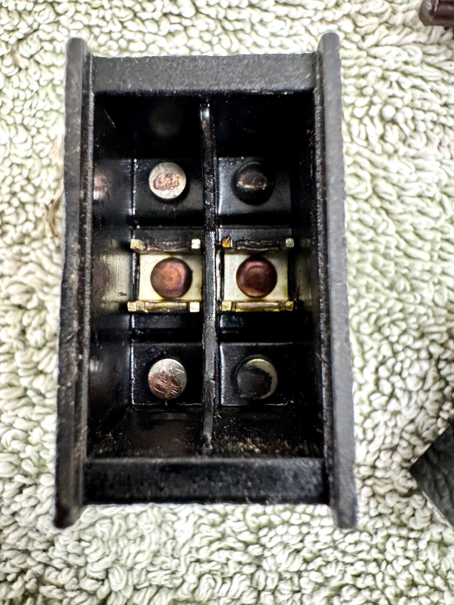
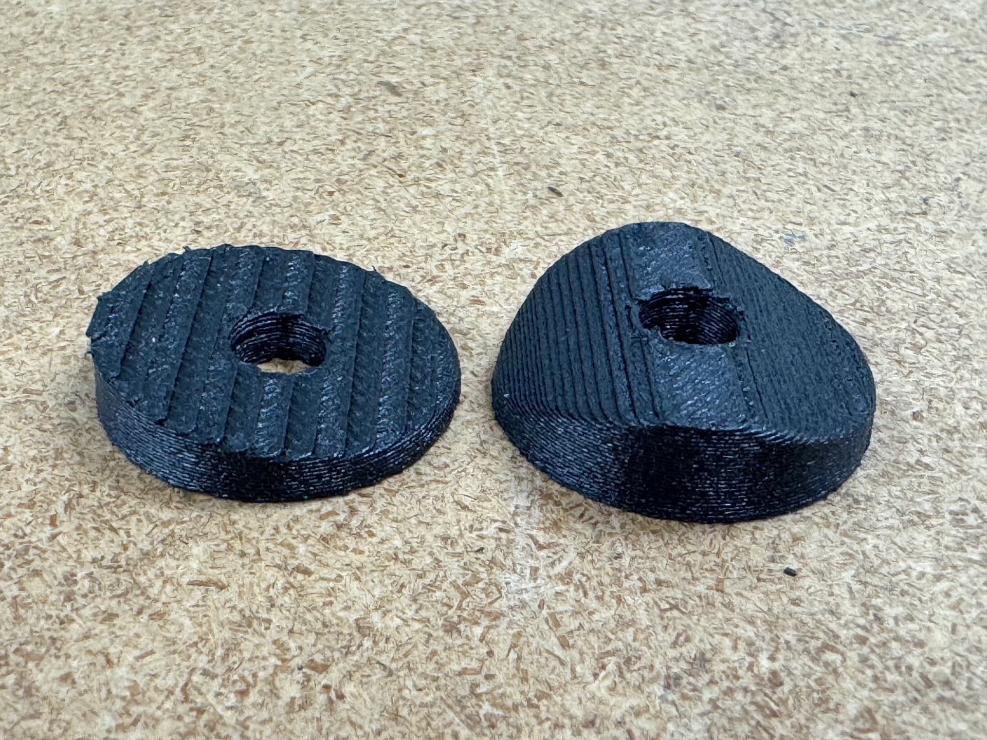
When doing testing to confirm the output tab operation on the back of the ignition switch, I discovered it was failing. A new one was ordered. Next, the positive wire from the middle of the cigarette lighter was toast. The insulation was rock hard and cracking through to the wires. A replacement was ordered. The wire going into the boot lid to power license plate lights was also failing. Hard insulation, and when cut and stripped several inches from the original termination point, the wires were corroded and brittle. Moving on to the front turn signals, at some point, those were replaced with Lucas units that function as both turn signals and running lights, but only wired for the former. The running lights are still wired to the little white thimble lights as per factory design. Not a huge deal, except the LED replacement lights don’t fit in place of the two filament bulbs. I also discovered that the right front signal wire had failed at some point (wires going into the bullet were broken and corroded) and the PO’s fix was to simply plug into the running light wire. That means the turn signal light output was less on that side of the car. Easy fix. As long as the seats and carpet wire were already removed, this seemed like a great opportunity to grease the front prop shaft u-joint. When removing the rubber access cover on the transmission tunnel, it crumbled in my hands. Another replacement part to order.

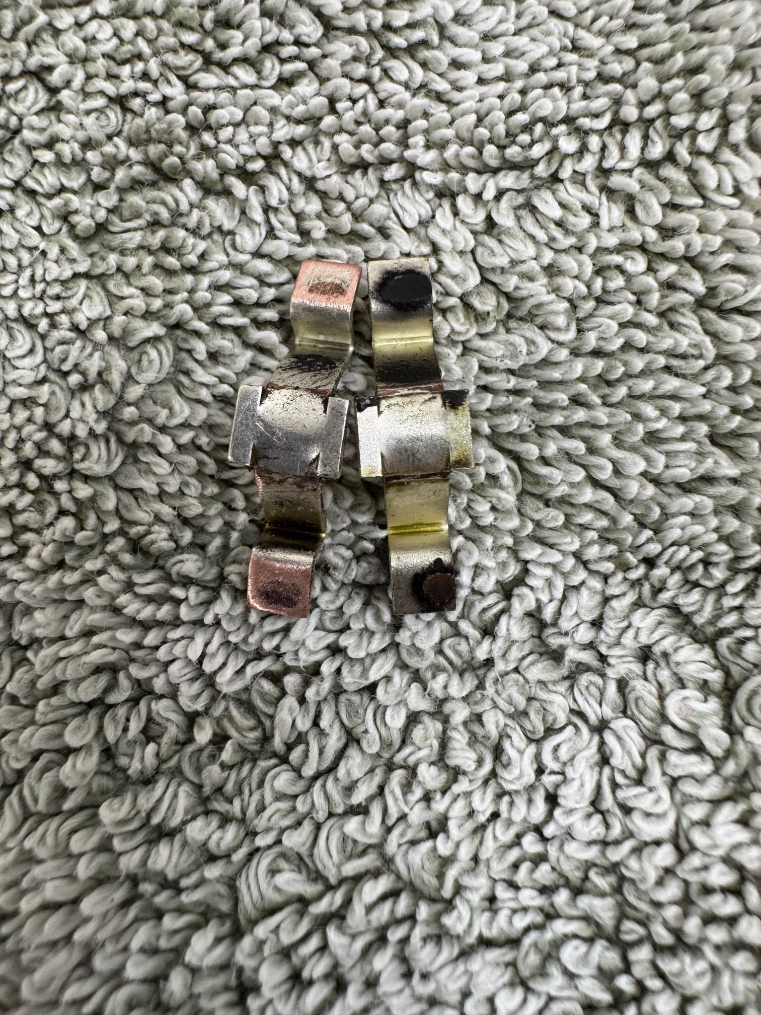
I’ll skip all the details my flag connector journey except to say that I was finally able to find a set of affordable crimpers from Ferrules Direct for the non-insulated style that work well. I also used their terminals to ensure compatibility. If you go the insulated route, crimpers are easy to find, but some of the quality insulated terminals available through sites like Mouser and Newark appear to require special crimpers to avoid cracking the insulation. Don’t ask me how I know…

1 „Gefällt mir“

Rather you than me, John!

All I can say is that I admire what you have done so far and declare that car electronics is a very weak point in my knowledge!

Tim

Thanks Tim, it’s not exactly a strength of mine either. We’ll see if that’s an understatement when I reach the testing phase.

One thing I didn’t mention earlier is that my plan to banish bullet connectors from the system has changed. Things like the taillights, turn signals, running light, dash light, cigarette lighter etc, are all terminated with bullets. To change that to something else means that if and when any of those items are replaced, I need to rewire them as well. Also, in those instances where I need to branch a circuit from another wire or daisy chain wires, such as the brake lights, the bullet connectors are actually a good, removable solution. As a result, my final harness is a mix of bullets, Deutsch connectors, flag terminals and straight terminals. AAW recommends this six-sided ratcheting bullet crimper. It’s worked well for me thus far.

Parts finally started arriving, which allowed me to complete the harness install. A few minor issues arose during the testing phase, but only one really flummoxed me: the wipers. It turns out the wiring was fine, but the grease in the drive mechanism had seized. That’s a straightforward fix and a lot cheaper than a new motor. I still need to clean up the routing of the under-dash wires and cover it with split loom, but that’s a project for tomorrow

These photos show the back of the dash, and the under-dash area prior to tidying up the wire routing and adding the split loom. The ground wires run to the two lower dash bolts, while the remaining wires are handled by eight Deutsch connectors and a pair of spades for the heater fan. That should make future dash removal a little easier.

The 3D printed glovebox is done. A hatch in the back, affixed by magnets gives access to the fuses and three relays. The six remaining relays are accessed beneath it. The inside will be flocked before the final install.

Another unplanned mechanical fix that’s required is the driver’s side window. The third time I tried it, it stopped. A quick grab of the cable revealed a lot of slack, so it either broke or jumped a pulley. But before it did, the speed was impressive.

My goal is to wrap up the loose ends over the next week, then turn attention to the rest of the interior.

-John

4 „Gefällt mir“

John
Some time back you were talking about using a German weave carpet, did you go ahead with that and do you have a manufacturers name and code
Tony

Tony, it proved too difficult. I was unable to find anyone with patterns in the US who would use that carpet. I decided to stick with a known quantity for fit and went with Sue Miller. It’s a tuft, so not original, but she does follow the original edging locations, which no one else seems to do. Unfortunately, it’s been on back order for a while. Fingers crossed it finally ships in the next few weeks. The German Square Weave is available here: https://www.upholsterysupplyusa.com/products/german-wool-square-weave-carpet
Based on photos of the original, the pile appears a bit shorter and the spacing between the loops is a little larger, which allows the backing to show through, particularly when bent around a curve. It’s also expensive. But it is nice and is as close as I’ve seen in automotive carpet.