Read carefully. Collect all your documentation. You may be able to contact an executive that can help.
I don’t want to be the bearer of bad tidings, especially knowing how long you have been waiting. But I had a similar occurence a few months ago, with UPS, and the only way I was able to obtain a satisfactory solution was to refuse delivery of the item. Even after that was done, I had to make several additional attempts before the charges were removed from my ‘UPS account’ (which was created by them, solely for the purposes of the tariff charges).
In my case the shipper declared the item under the incorrect HTC code, which caused it to be assigned a 200% tariff. If my case is typical, the shipper selects the code(s); UPS merely applies the tariff(s).
Neither the shipper nor myself were ever able to change the HTC code. After many weeks of effort I finally refused shipment and UPS returned the item to the shipper.
Here is a link to the government’s searchable HTC code database. I poked at it a bit using your codes and I can’t say I know any more now than I did before.
1 Like
That looks like an error. I had a similar issue with a FedEx clearance and was able to get it corrected by contacting their import clearance department.
1 Like
Luckily for me, my brother works in importing& exporting and is assisting. He says I should be paying 35% for the ECU & 10% on the wiring harness so hes working on my dispute for me… lets see how this goes
1 Like
Decided I had gotten as much “footage” of the general swap headaches, minus the fuel system so I decided to wrap up another video. It’s longer than I usually make them and it’s full of slow work, kinda typical of what it’s been like… I also did a terrible job of framing on this so that was fun..

The good news is that I’ll be moving on to the fuel system and recording that for its own separate video. There’s still a ton of little things to do but none is worth documenting in video. The work that is worth documenting is related to the fuel system so that will be my primary focus now. Also, the other cars were being needy so those should no longer be a distraction meaning I can focus on the final stages of the Elan, once and for all! New target is driving it, one year after buying it…
2 Likes
@2mAn Hi Simon, Nice! Nice video too! I would say: ![]() Keep-up-the-good-work!
Keep-up-the-good-work!![]()
So, new target is then: Driving = 2Day+32Days! Good luck, I bet you´ll succeed!
Best, Sam.
1 Like
Oh man, thats sooner than I thought! Here I was thinking I relieved some of the pressure haha
1 Like
Good to see the progress, and can’t wait to see you on the roads in spring! Also, thanks for including my Elan in your Queen’s English pics ![]()
1 Like
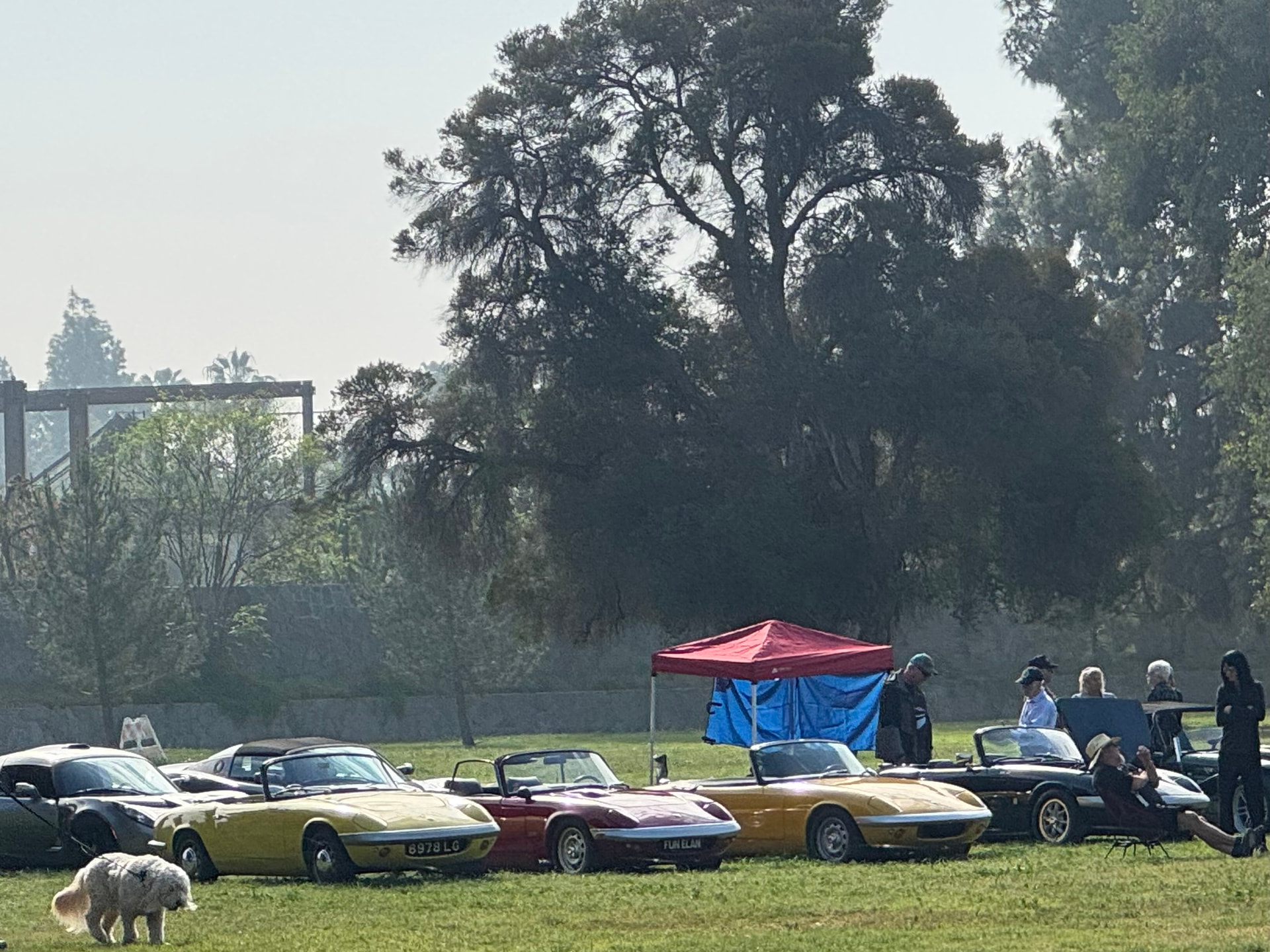
Of course, wish I had a chance to say hi! Which one was yours?!… I loved the fact that there was 3 Elans there and all 3 were different. S1, S2 and S4 (I believe), my friend Matt’s dad has owned that red one ‘FUN ELAN’ plate forever and it recently went through a refresh.
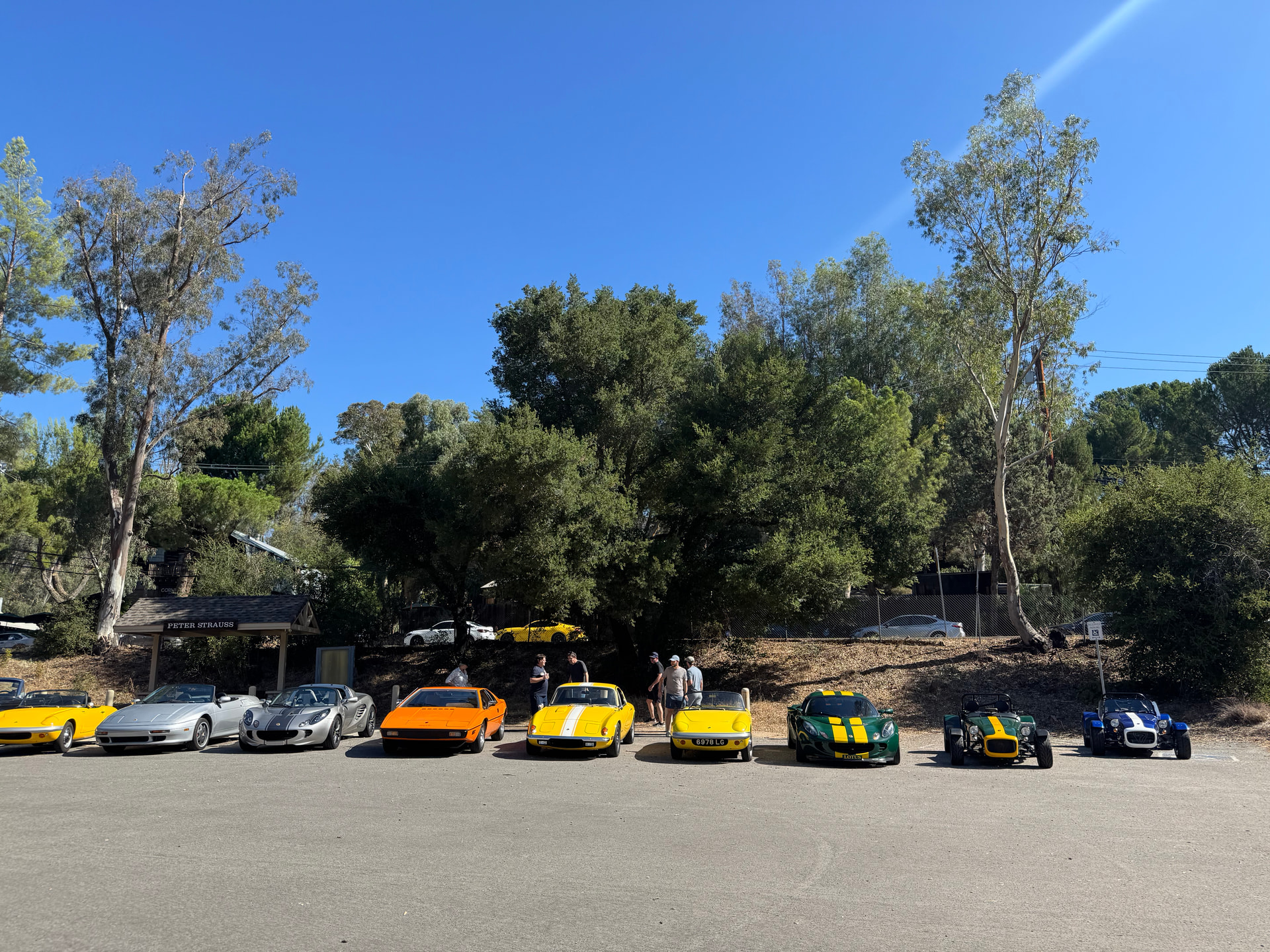
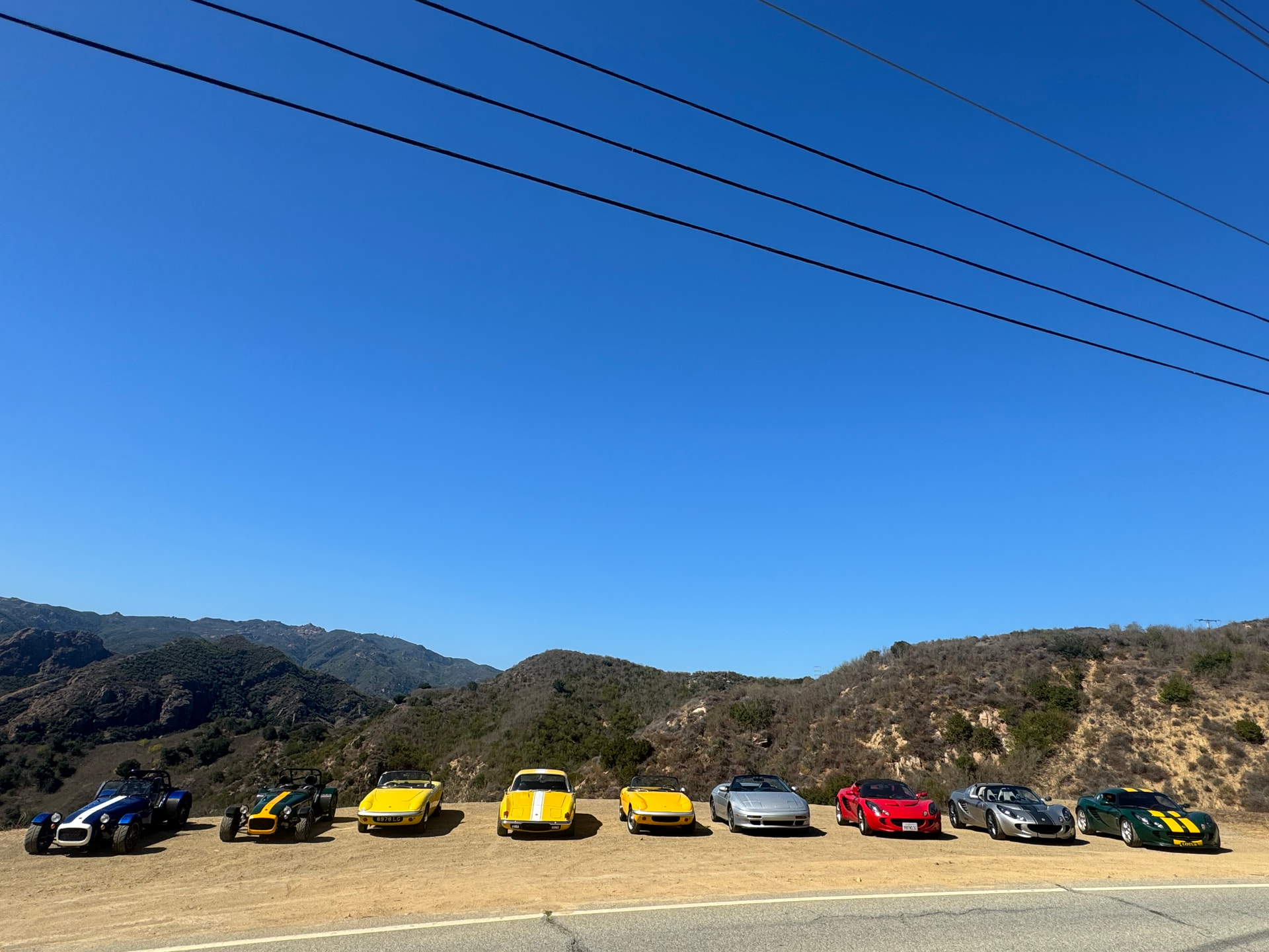
I had to leave early for family commitments. Mine’s the yellow S1 ‘ELAN98’. There were actually 4 Elans (pic below) - maybe even an S1, S2, S3, & S4 line up. I’ve met Matt (and was chatting to his dad) - he brought his M100 to the very impromptu Lotus shoot at The Old Place & on Mulholland (also pics below)
2 Likes
Starting to prepare the fuel system, still on the fence about the swirl pot as the fuel tank itself is already a baffled unit so not sure I need/ want to add the redundancy/ complication, but we’ll see…
For now, I wanted to wrap up some of the smaller, annoying items up front so I can be ‘officially’ done with the engine bay. Nearly there, still a few things to wrap up…
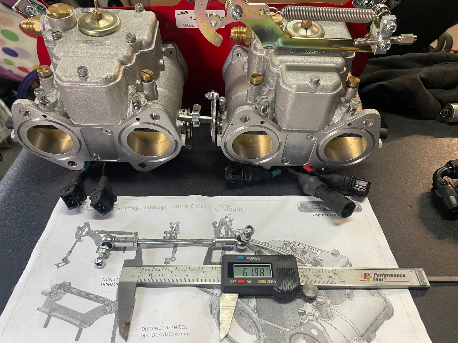
(1) Jenvey Heritage ITBs have a shorter mounting flange than Webers so the studs had to be removed, and the 5/16” holes were re-tapped to have some clean threads, the studs looked like they had some gray antiseize added a LONG time ago that was gumming up the threads. The #4 & #3 cylinders were a bit of bear to tap with their space so close to footwell/ pedal box area. Done!
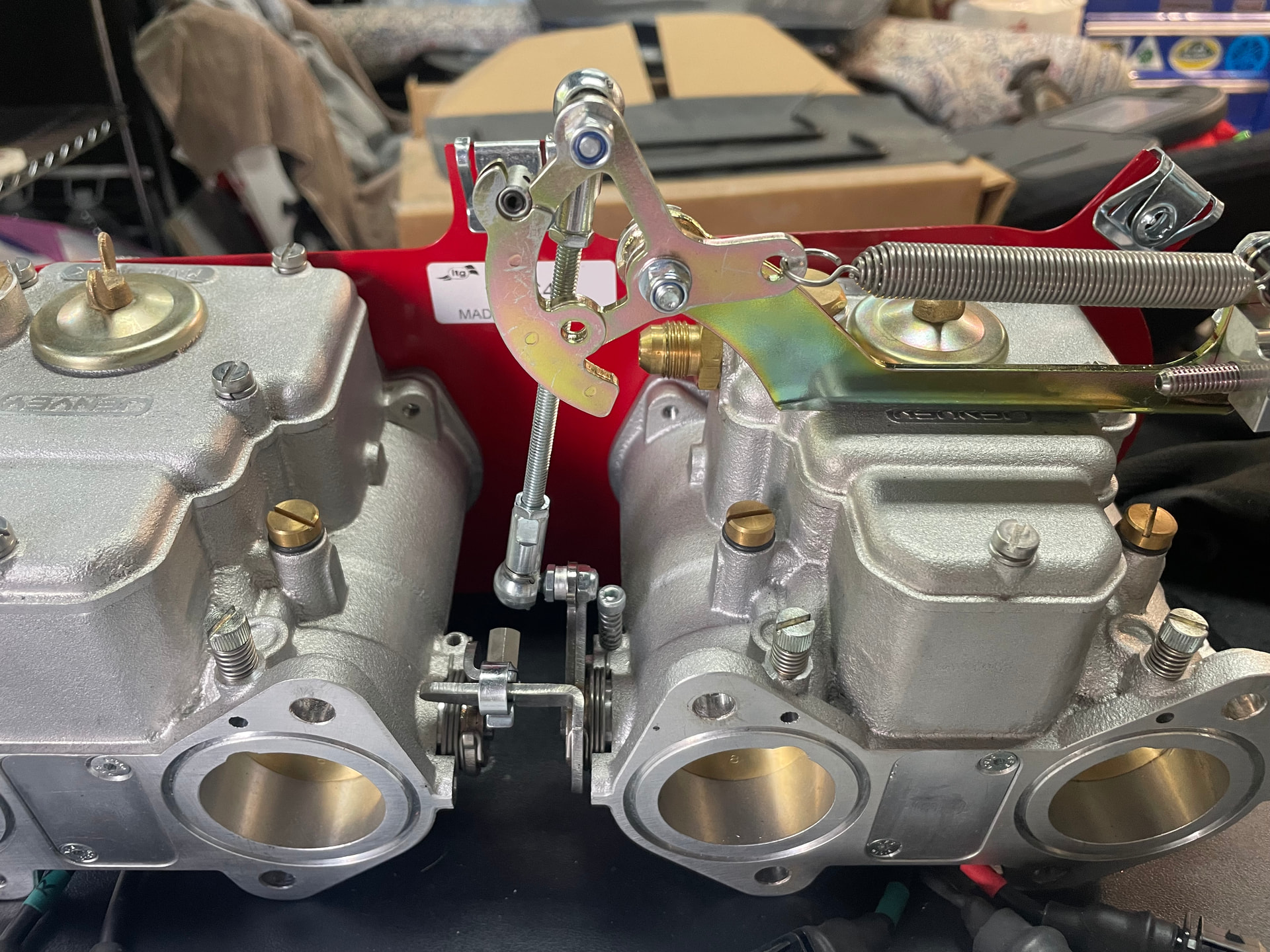
(2) The throttle shaft for the Jenvey Heritage ITBs that was ~3-4mm too long and needed to be trimmed. I avoided this because I hate cutting up new parts, but it went relatively easy and is now done. Would’ve been easier if Jenvey had just provided the correct length threaded arm
(3) Finally, while I want to believe this distributor block off plate will stay in-situ I wanted to make sure there’s a hold down which will use the Original distributor hold down bolt. CAD model prepped ![]()
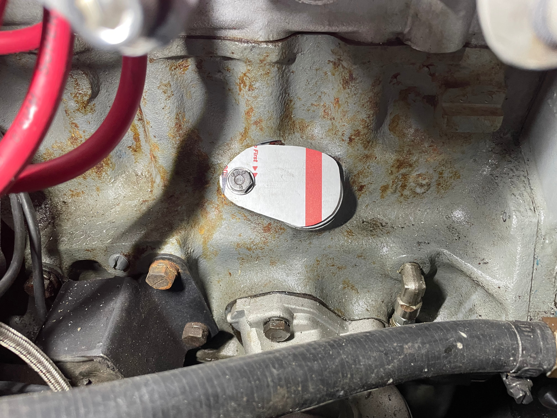
Getting closer, one annoyingly small project at a time…
1 Like
Fuel system
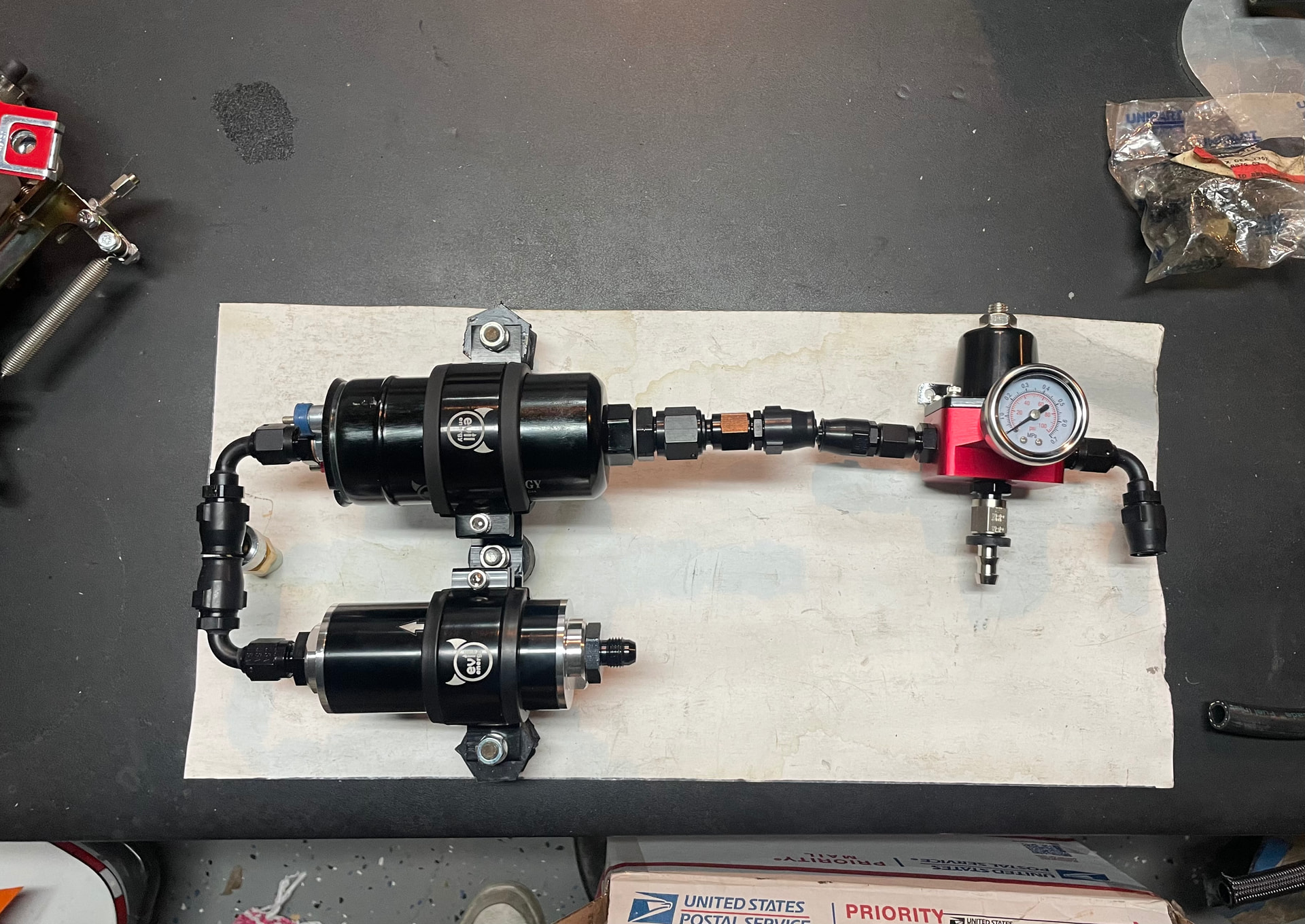
I’ll go into detail on this in the video, but basically I couldn’t do the original plan with the fuel system update/ upgrade. Something about 10# of stuff in a 5# bag… the white paper is the space I am trying to fit everything into. The fuel lines are likely to be quite short so I am hoping to find an alternative before I cut a 2” fuel line. Heres the mockup I finished up this past weekend.
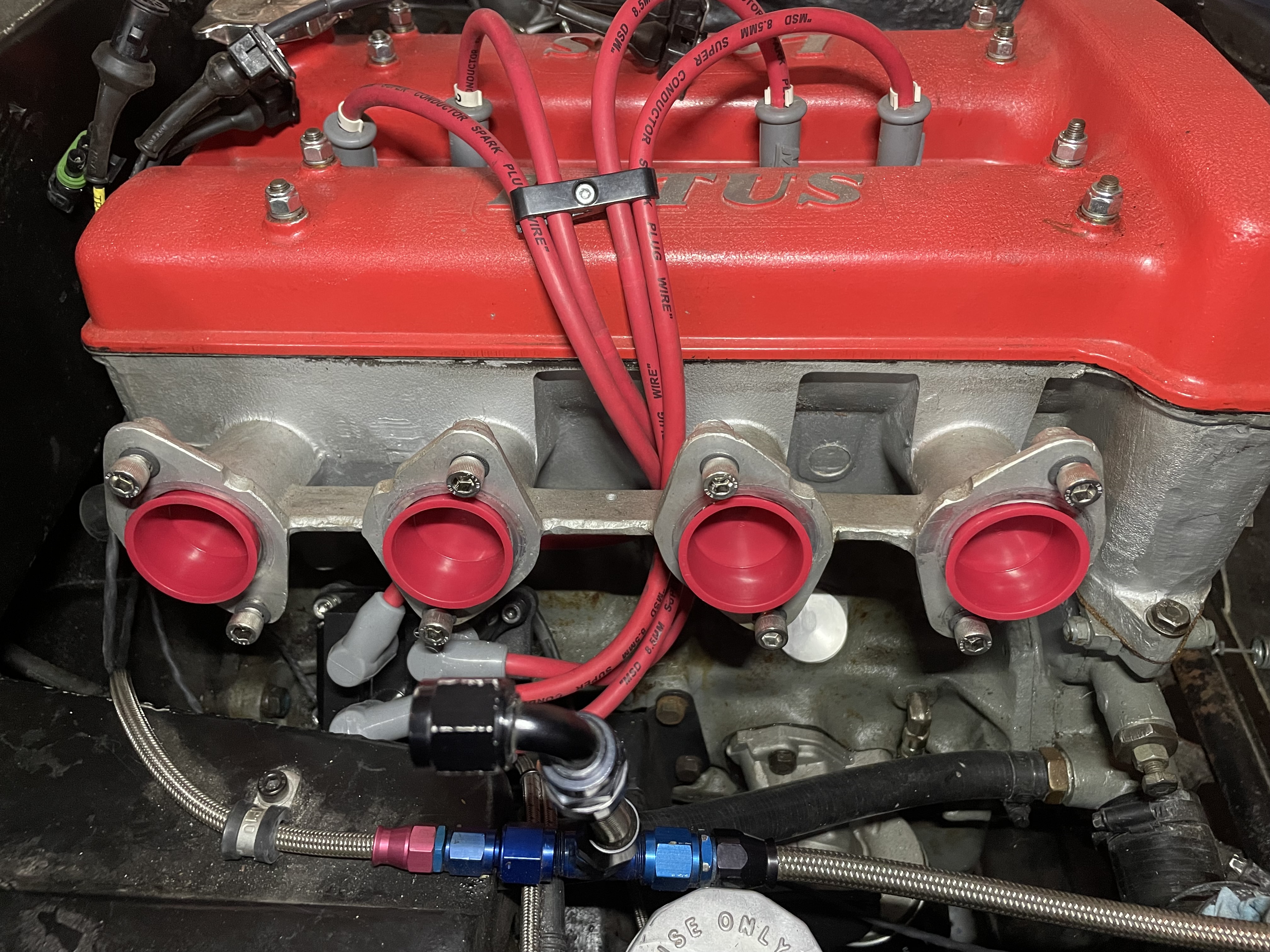
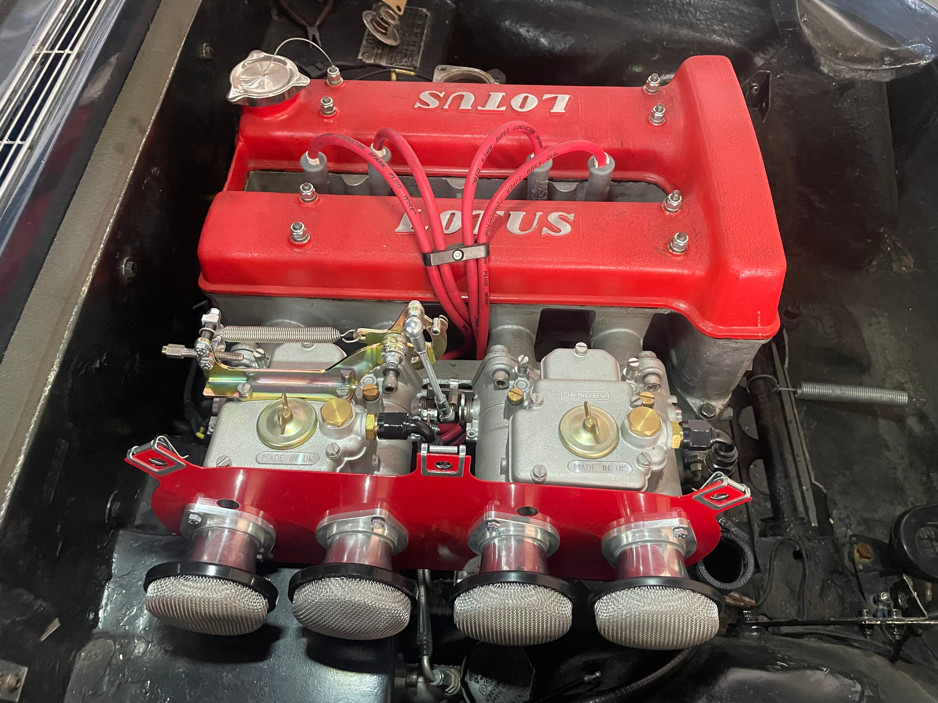
And finally… The Full Intake installed. Only got 5 of the 8 bolts installed before I ran out of time, but couldn’t resist admiring the view and taking a pic to share with everyone.
2 Likes
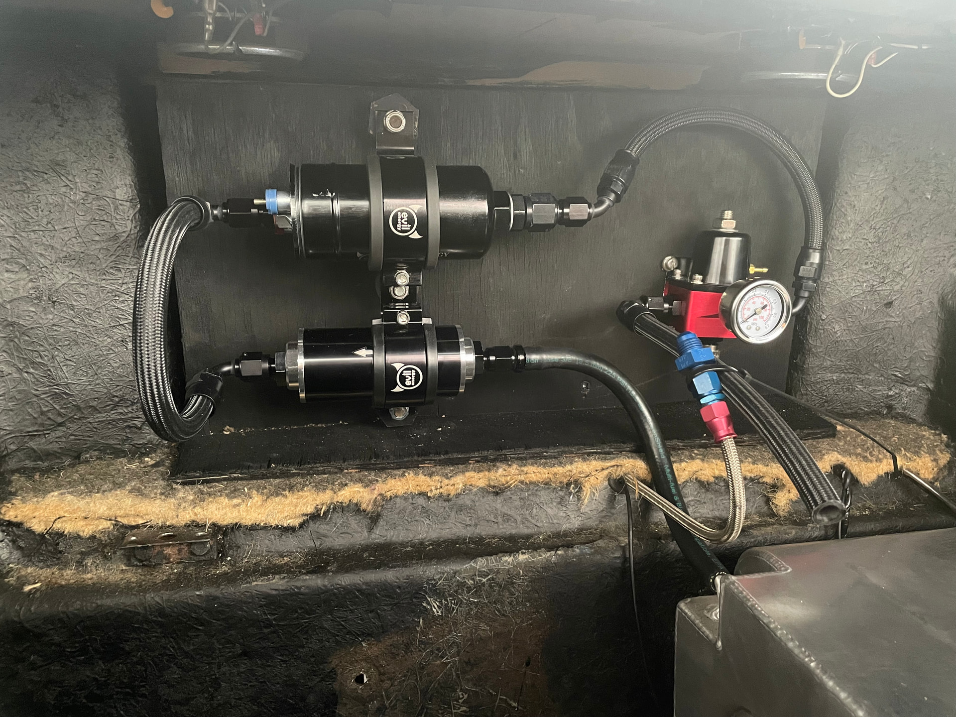
Looks like quite a few adapters, are they all needed? Yikes.
I might suggest relocating the pressure regulator to another place. Mine is bolted to the inner fender well near the carburetors.
2 Likes
In the spirit of ‘for what its worth’ those gauze covers on the air trumpets completely disrupt shape of the entry to the trumpet and reduce the airflow. If you are using a filter, you don’t need them.
… and on the subject of filters, the best filter arrangement is the original design, feeding cold, slightly higher pressure air from the plenum in front of the rad. For maximum performance, use a K&N (or ITG) cone filter in the plenum and use an enlarged airbox that doesn’t mask the rear carb inlet.
Good luck.
3 Likes
@wdb It looks busy for sure, the teflon fuel line hasn’t been cut yet, and I’m hoping to reduce ( simplify ![]() ) the system, so this is ‘phase 1’ although this is closer to the 3rd or 4th version I was considering. As for relocating the FPR under the hood, I have considered it, but for many reasons I dont want to add a lot more work, plumbing, complexity to the system. K.I.S.S. though this may prove to be foolish, though I wont know until its running (or not running properly).
) the system, so this is ‘phase 1’ although this is closer to the 3rd or 4th version I was considering. As for relocating the FPR under the hood, I have considered it, but for many reasons I dont want to add a lot more work, plumbing, complexity to the system. K.I.S.S. though this may prove to be foolish, though I wont know until its running (or not running properly).
@Andy8421 I am also not a fan of the filters’ function, their form is nice… but thats not what Im ultimately after. However these have already been paid for and I don’t want open stacks. I plan to drive with no hood until I feel safe that its dialed in, so these are the ‘temp’ filters. The ITG filter will be the final version of the ‘its finally running reliably.’ I may add the full airbox later down the road.
I plan to get the car dyno-tuned with this setup and once its been optimized, I will run the dyno tests again with no filters…and finally with the ITG filter. I have read the ITG is the best filter with the least restriction. When I am ‘bored’ and looking for a new project is when the OEM-style airbox will be evaluated. I mainly needed the backplate as thats where the intake air temp sensor will be mounted.
I agree with wdb, far too many adaptors. Surely you can make do with 2 or 3 joining those top bits together. Find another fitting supplier!!
Mike
1 Like
Keep in mind, the original design was assumed to have more space, but when all shoved together the link between the pump and the FPR is several junctions. You guys are seeing what I am seeing though, ideally I can have the pump mounted directly to the FPR with one fitting… the whole setup is in my car, just need to take a ‘long lunch break’ to head over to the shop
Alright, put some work in and cut a panel to “hang” everything from. After visiting the AN fitting supplier with my requests he gave me the best solution that he said is available. The filter and pump situation required rotating the 90 fittings to squeeze some hose in there because there wasn’t a premade hose that would fit, and the pump to FPR got a 45 (or was it 30) to go over the FPR and back around. He said that two couldn’t be solid mounted together as they would be vibrating at different frequencies and something would break. I was a bit annoyed over the whole deal but moved and am happy with this result.
Somehow I’m missing one fitting (probably during all the fitting shuffling on the last visit) and I think I want to swap out the straight drain for a 30 or 45 to angle the return towards the tank… getting closer …
3 Likes
That layout looks better. Have you applied power to the pump? That mounting location could make for an unpleasant amount of noise in the interior depending on the sound it makes.
No power yet, its not a good idea to run these pumps dry… however, I share your concern and I can assure that I have prepared for that nuisance and have a plan to deal with it… ![]()