Hi All,
Coming to the end of a plus 2 S130/5 restoration and now refitting the dashboard and electrics.
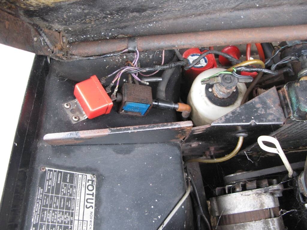
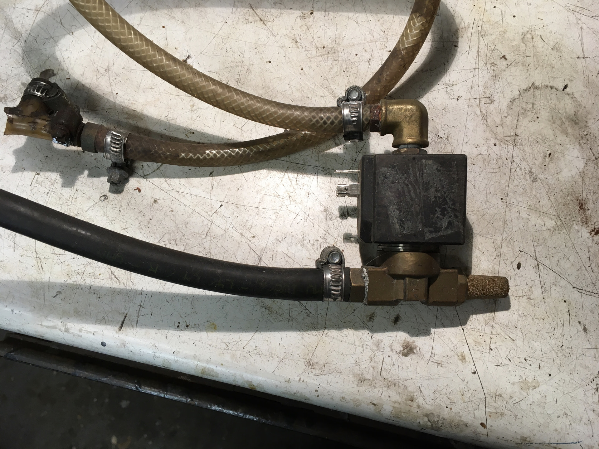
I am reconnecting the lights and need to understand the wiring to the vacuum system. There appears to be a relay that is close to the vacuum solenoid which has various loose wires from it. Can someone confirm the wiring diagram for the vacuum system. At the moment the headlights main beam can come on with the lights down (which I don’t think is correct), and the wiring at the solenoid is not correct too.
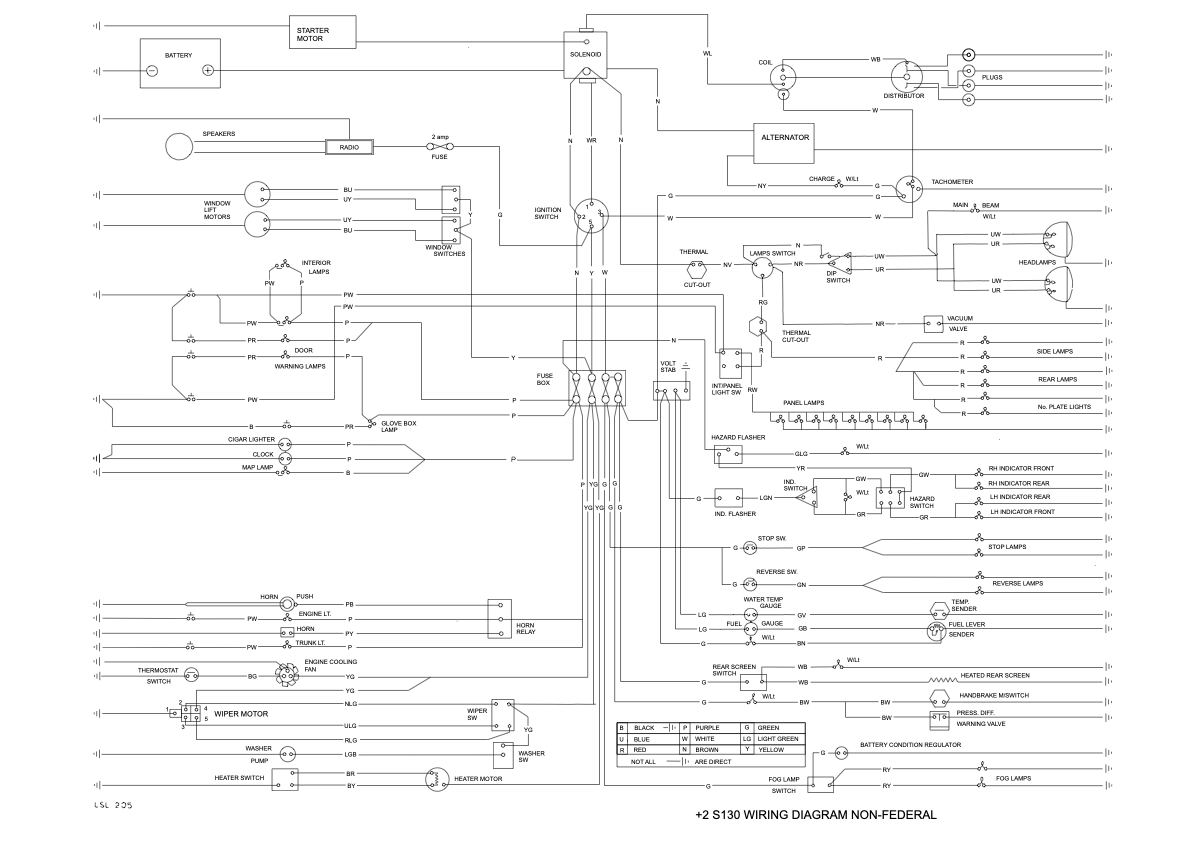
Looking at the +2 S130 wiring diagram for non-federal, I cant see a relay on there.
I am assuming that Brown/Red & 2x black goes to solenoid, and when light switch is on, that this then operates solenoid and gives a power output to operate the lights through one of the back wires b(is this through the relay and what connections are at the 4 points on the relay).
On the relay I have 2x purple (1 which has come loose from a connector & 1 which has a white/red also spurred off it), 1x purple/yellow, 1 x purple/black. Would appreciate comments on how these fit. My guess is White/Red - 30, Purple (white White/Red is spurred off) - 86, Red/Black 85, loose Purple ??? Or should this replace the White/Red.
Can anyone advise please?
Many thanks