In getting the engine back together after having the head, pump, sump and other associated bits off, I’m having a weird problem with valve clearances. If it makes any difference, this is a Stromberg head that has been modified to Dave Bean Stage II specs.
Before taking it all apart I checked the clearances and found all 4 intakes to be at .004" and only one exhaust was correct (exact figures are on a scrap of paper down in the garage). I measured the shims, did the math, ordered some new shims and carried on with the other work.
After re-assembling everything I found the clearances way off. Fair enough, since everything had been disturbed and I wasn’t the last person to have it apart so I can’t account for anything in the ‘as found’ condition. I took the measurements, took the valvetrain apart again, re-measured the shims (they were all what I thought they were), ordered a few more.
When that order of shims arrived I verified their sizes, installed them, re-assembled the valvetrain again, checked the clearances and found many off again, but to the extreme in the opposite direction. Some that had been very tight were now very loose. Pull it apart again and do some math, swap some shims around between various positions and my growing collection, put it back together and one more is in tolerance, but the very loose ones are now very tight again. The excursion of these changes have been much greater than the change in the sizes of the shims. Bigger shim to reduce clearance, smaller shim to enlarge it, right? And it’s only five of the eight that are being troublesome like this, the ones on the exhaust side being the worst.
Additional details:
-When I reassembled, I used the same type head gasket as before but converted from head bolts to studs since DBE was out of the bolts.
-Head torque has not been disturbed since the head was re-installed.
-Every shim has been verified (some more than once) with a Mitutoyo digital micrometer than has been calibrated by an A2LA-accredited vendor within the last 60 days (borrowed that from the tools I use in my job ).
-Everything was well-oiled during reassembly.
-I verified during each reassembly that the camshafts had not been swapped and that their bearings were fully seated.
-Upon each reassembly I verified that the timing was all still lining-up after pulling the engine through a few cycles.
-The old cam cap nuts were discarded and the new ones have been torqued per WSM specs during every reassembly.
-This is not the first shim-and-bucket valvetrain in which I’ve adjusted clearances but this is the first time I’ve done it with a Lotus Twin Cam.
These seemingly illogical failures to get the clearances where they should be is becoming aggravating. Am I nuts or is there something I’m missing here?
Also check what shim thickness are you using and what is the shim pad step size inside the follower as you can have the top of the retainer contact the bottom of the follower rather than the shim contact the shim pad if the shims are to thin for you retainer and follower combination.
On my first +2 the Collet retainers were touching the underside of the Cam Followers and not the Shim touching the Shim pads.
I solved the problem by fitting new Collets. The Collets were too small on the outside dia which let the Collet Retainers come up too high and touch under the Cam Followers/Buckets.
Until i realised what was happening i could make no sense of Valve Clearances.
Alan
If none of the posts from the previous poster’s help I would be inclined to check the fit of the followers in their respective sleeves, and flatness of shims / valve tips / followers (pads underneath included).
I have seen clearance issues on engines with too much follower clearance which allows the follower to tip and give a different figure each time. Also, poorly ground shims (ie not completely flat all the way across) will give problems.
I also saw this problem on a BDA which just about drove me to never touch one ever again : 16 valves isn’t always better when they’ve all got problems!
If I remember correctly, the shims all rise above the
tops of the retainers (I’d think that the shims would be much more difficult to remove if not) but I’ll double-check this along with the other suggestions.
This is why I pay people to set valve clearances on my head rebuilds (Just kidding, I do it myself)
+1 to what Rohan and Alan said regarding the follower contacting the retainer.
Have you gone back to the original shims you removed from the engine (the ones that got you .004” on the intake) to see if they yield the same clearances as before? Trying to obtain repeatable results is usually where I start when chasing ghosts like this.
Are you re-using any shims that have a slight depression worn in the center where the valve stem previously made contact. If so, then it’s imperative that you measure the shim at the center by using a micrometer. It’s round anvil will fit down in the depression and measure the actual working thickness of the shim… which is something less than the shim’s rim thickness. Then make absolutely certain that you install the shim with the depresion side down against the valve stem. Screw-up and install the shim depression side up, then the tappets inner flat mating face will bridge across the depression, contact the shim’s rim area, and the resulting clearances will be short (tight) by the depth of the depression.
Use a micrometer to measure the shim’s ‘RIM’ area (NOT in the center depression), or…
Use a caliper, the jaws of which skip across/ cannot measure down into the depression…
and any such measurement will be greater than the shim’s working center thickness by the depth of the depression. Do the math, calculate an expected (but wrong) clearance, then install the shim depression side down against the valve stem, and the resulting clearance will be greater (looser) that expected.
Every used shim has two thicknesses… the rim thickness is greater, and the center depression thickness is less. It is okay to use either thickness, but you must keep your head engaged and match your measurement to how the shim is installed.
Depression up against the tappet = effective.rim thickness.
Depression down against the valve stem = effective center thickness.
Seemingly random clearance problems are typically due to re-using old shims that have a worn center depression, and then installing the shim without paying attention to which side goes down against the valve stem.
That and the outside square edge of a shim interfering with the corner radius of the retainer’s shim pocket can drive you nutz if you don’t account for them while measuring and installing shims.
Shimming valve clearances is really quite a direct, B follows A process as long as you account for the details. When I read about someone doing ‘correct’ math then still experiencing ‘random’ unexpected results, I immediately suspect the above issues.
Nutz? A shim depression can result in mental depression.
I had this problem a while ago and it was caused by what others have suggested-the shims not projecting above the top of the spring retainer and the cam follower resting on the top of the retainer. Sorted out by an expert who had seen it before!
I recently got a set of new steel followers from Burton and these have pads that ‘reach down’ inside the retainer so even if the shim doesn’t reach the top the follower will rest on it.
Hmmm… So, you’re saying the inside face of the tappet’s crown is flat all the way across? If that’s the case, then having the spring retainer’s shim cup extend above the top of the shim (ie, shim is recessed into the cup) could very well result in an unexpected valve clearance result. I hadn’t responded to this notion earlier, because it wasn’t consistent with my experience, and I didn’t want to speak until I’d checked some tappets.
I just checked my stash (about 30+ old retired A026E0024 tappets I’ve collected for no reason). Flip them over and look inside, and all of them have a raised pad in the center… about 1/2" diameter by 0.070" (1.78mm) tall. If you buy from aftermarket Lotus sources (Garry Kemp in the UK ir JAE in North America… and others), tappets are also availble with thicker crowns (taller center pads) to accommodate re-ground cams without resorting to unobtainium thick shims.
I’m not saying it can’t happen that the tall rim of a spring retainer’s shim cup touches the inside of a tappet before the shim does. I’m just saying that “IF” a center raised pad is present inside of the tappet (the only kind I’ve ever encountered), then the rim of the shim cup would have to stand up above the shim’s top surface by the height of the tappet’s center pad… plus a little… 0.070"-plus.
Or were there Lotus tappets that are flat inside, without a raised center pad, and I’ve just never seen one? I’m always willing to expand what I think I know about these engines.
Noted. I have two types of shims, some the ‘disc’ type and some the much smaller ‘cap’ type. Some of the disc types have a chamfer around the edge of one face, one or to have it around both edges, some do not have a chamfer. I’ll put this on my list of things to check, but so far they’ve all fit smoothly.
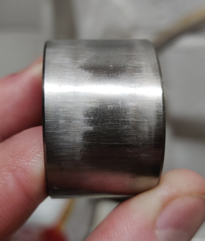
The WSM says .0014 max between the follower and sleeve; my thinnest feeler gauge is .0015 and it would not go into the gap on any of them and they all feel nice and smooth and free of wiggle when I slide them in or out. That said, the wear-pattern on the follower in the picture is typical of what I’ve seen on all of them. To my novice eye it looks like their motion hasn’t been completely free of tipping but I understand that a tiny amount will happen with even the smallest gap. Does it look OK or suspicious? How much difference in diamater should I see between the worn areas near the edges and the unworn central area?
Follower pads: I have checked two of them, measuring four places around the circle of the pad and on one all four were within .0005 of each other; on the other one they were within .001.
As for shim flatness, that’s going on my list of things to check next session in the garage.
I used to have an Esprit. I did the valve-adjustment with it once and didn’t have anywhere near this amount of headache with getting the 16 clearances right! That head had about 23K miles on it vs maybe about 1K since my TC head was rebuilt before I owned the car. The rest of the job with that engine, dealing with all the belts in situ…I never want to do that again!
Doesn’t seem to be an issue since all shims are tall enough to protrude from the retainers.
If I’d known that this situation or question would come up, I would have tracked each one…but alas, when I ran into problems I swapped some around and any not in use got set side with no more ID than their thicknesses (although based on my notes, I may be able to reconstruct that setup). But in the spirit of repeatability, during today’s session I spun the shafts a few times then measured clearances again, not having disturbed anything since yesterday’s measurements. For today’s on each one I measured, spun the cam twice, then measured again and all were the same before and after two spins. Here’s what I got:
Yesterday
I E
1 .009 <.0015
2 .012 .012
3 <.0015 <.0015
4 .013 <.0015
Today
I E
1 .009 <.0015
2 .008 .011
3 <.0015 .014
4 .010 <.0015
But before yesterday’s attempt at adjustment, I2 measured .010, I3 .018, E1.021, E3 .021, E4.032(!).
According to my notes the initial measurements before the head was off were:
I E
1 .004 .008
2 .004 .011
3 .004 .014
4 .004 .016
Wow Mike, that is an impressive collection! I don’t know if I’ll know what I really need in time for that, but I still have your contact info and can get in touch if need be- thanks in advance!. Do let me know when you’ll be by this way in case you have time to drop by and see project in person! I have a biz-trip in your direction in a couple of weeks so I might be able to do likewise.