安全性と信頼性のために+2 loomをアップグレード中

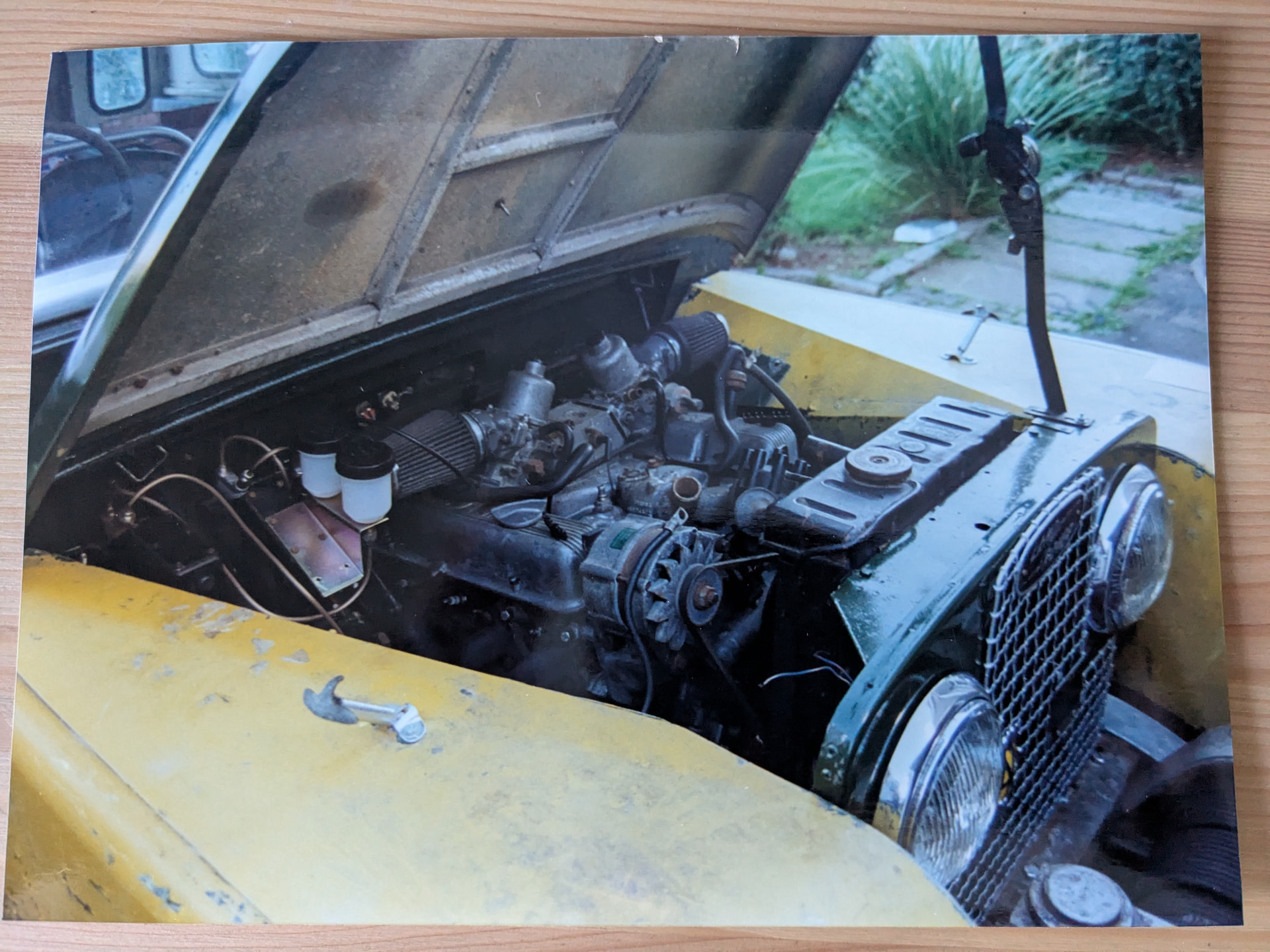
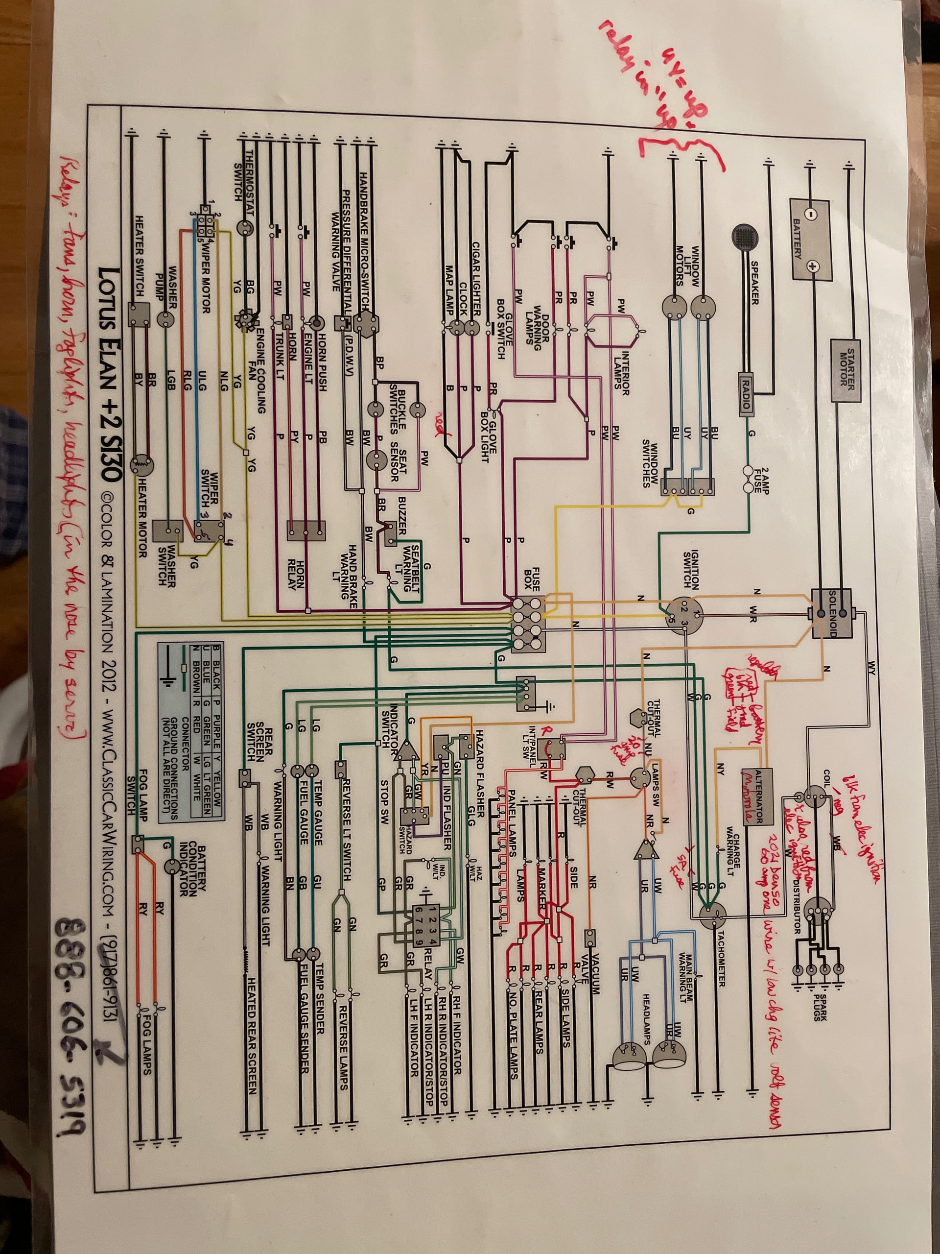
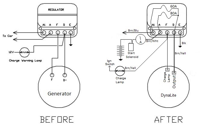
I would like to share details of my project aimed at modernising the wiring in my 1968 +2 vehicle. The original loom features a four-fuse loom and a dynamo, which has subsequently been replaced by an alternator. An electric radiator fan has also been added. While I am not a qualified auto electrician, I possess a foundational understanding of electrical systems.

My primary objectives are as follows:

1. Minimise the risk of malfunctions leading to fire hazards.

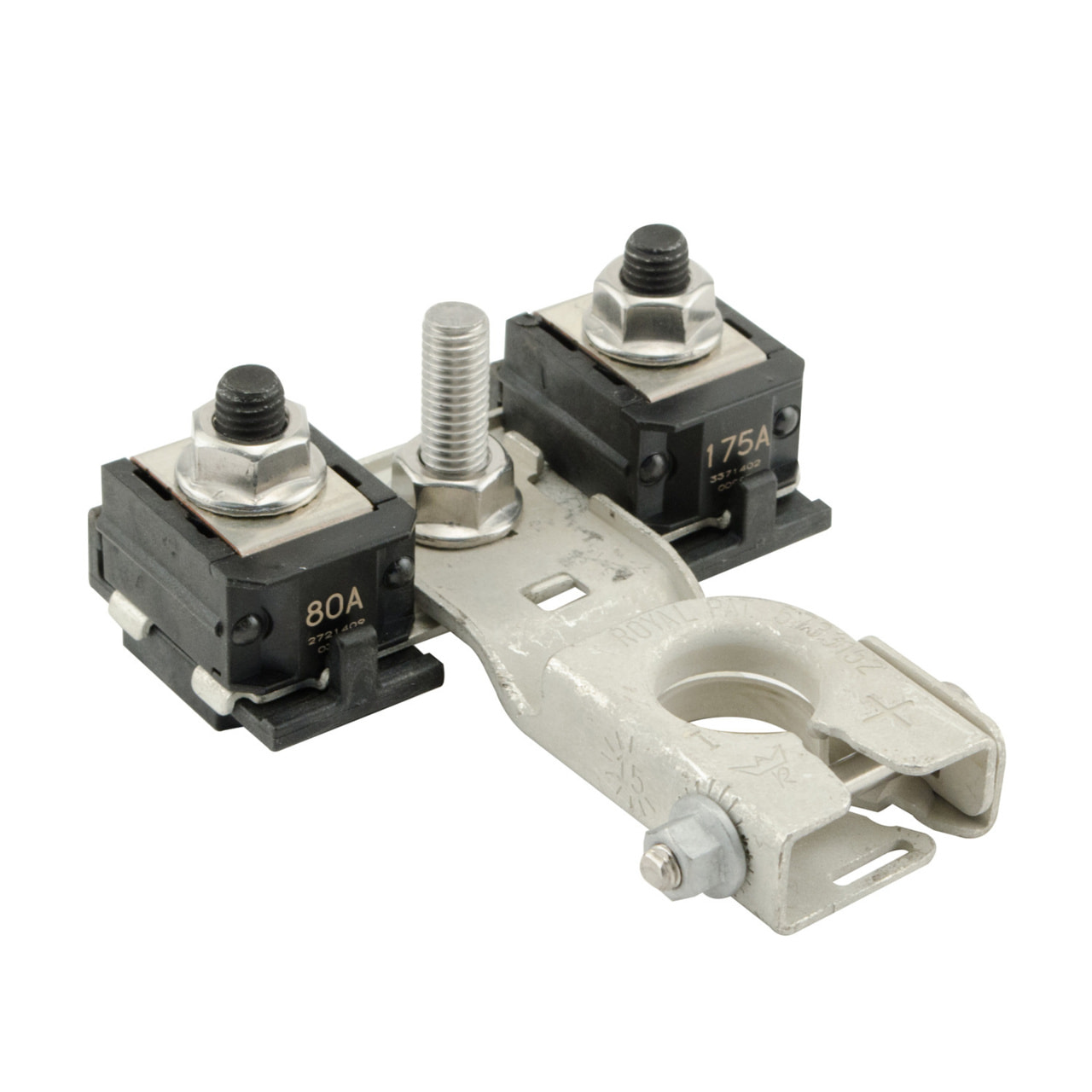
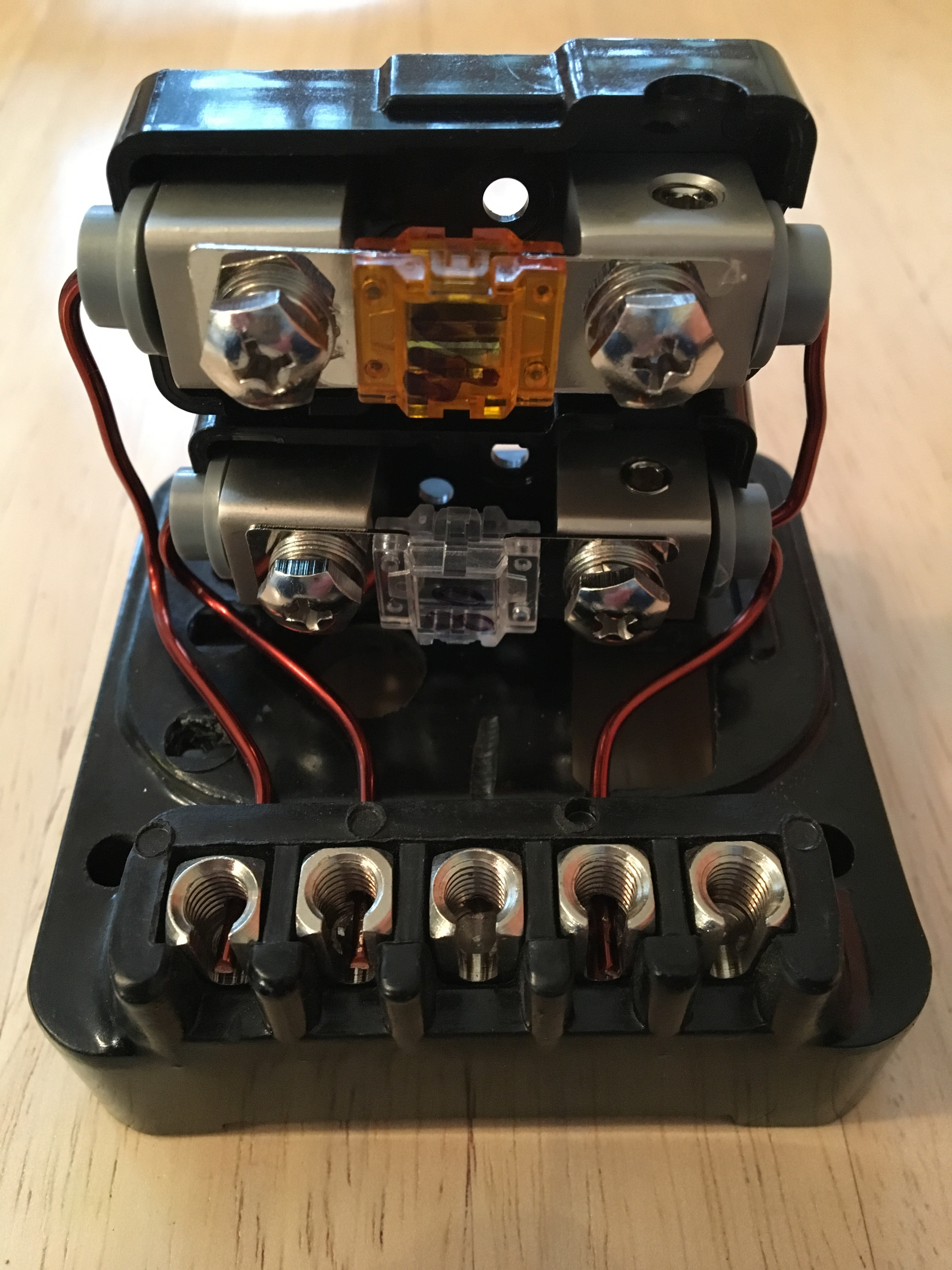
2. Enhance reliability by incorporating modern components such as relays and additional fuses and individual circuits.

I welcome any feedback or constructive advice from members who have undertaken similar projects.

There are several important considerations to note before outlining my approach. This is not intended to be a full body-off restoration; I plan to implement improvements in stages to maintain drivability throughout the process. Based on previous experience, these projects tend to expand and take longer than anticipated, hence the need for a phased methodology.

Outlined below is my preliminary plan:

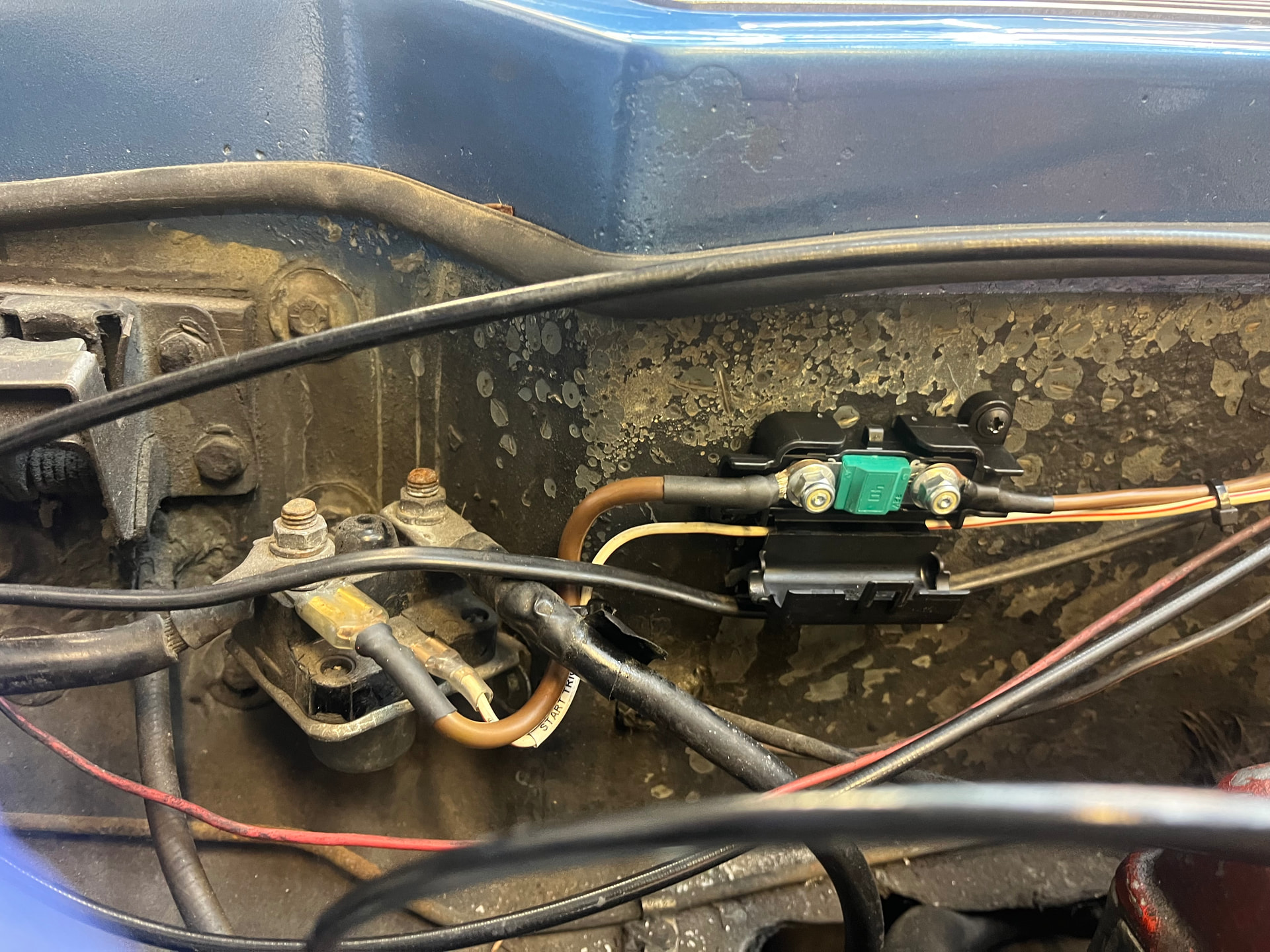
Stage 1 – Basic protection: Install fuses for the ignition switch feed and alternator supply.

Stage 2 – Conversion to electric headlight lift.

Stage 3 – Enhanced circuit protection through an upgraded fused board and relays.

Stage 4 – Electric fuel pump installation.

Stage 5 – Addition of hazard warning lights.

This sequence is provisional and may be adjusted as the project progresses.

Thanks in advance. J

「いいね!」 1

John,

My car is a 1968 S4 which I bought as a basket case in need a ground up restoration. My objectives were similar to yours. I am a mechanical engineer with basic electrical knowledge. Before I started the electrical work, a good friend who is an electrical engineer and old car enthusiast advised me against what I intended to do. I went ahead anyway, and although I am happy and rather proud of the result, I would say it has been the hardest and most time consuming part of my restoration.

Richard Hawkins

「いいね!」 2

I’m not an auto electrician either but I have worked on various old vehicles over the years and even fully wired one from scratch. It was a ‘55 Landrover, so it wasn’t exactly complicated though.

Here’s a few observations I’ve picked up along the way, in no particular order.

  1. The biggest cause of electrical issues in cars of this age is oxidised connectors. If there’s one thing you can do to improve reliability and reduce the risk of fire, it’s properly clean and tighten all connectors. Contact cleaner does virtually nothing in these cases, I’m talking mechanical cleaning with fine emery paper or a brass brush on a drill. Spade connectors can be tightened with a gentle tweak with pliers.

  2. Don’t skimp on connectors. Avoid the ones with the coloured plastic sleeves that you crimp with a simple plier-like tool. Invest in a proper ratchet crimping tool and matching connectors.

  3. If you’re making connections that are going to be permanent, such as splices etc, solder them then sleeve them with heat-shrink tubing. Every non-permanent connection is an added potential future point of failure.

  4. Use the right gauge of wire for the job that it is doing.

  5. Make sure your wiring is secure and isn’t going to vibrate and rub through on anything. Use grommets. Insecure wiring is maybe the second most common cause of problems and fires.

  6. Keeping wiring tidy is hard! Trebly so if you are adding to or modifying an existing loom. It’s easier to do a neat job if you’re starting from scratch.

  7. Modifying old existing wiring can be problematic. Insulation can be brittle. Wire can be oxidised and need thoroughly cleaned before you can crimp or solder to it. You can find yourself wishing you’d just replaced the entire loom.

    I’ve added some pictures of Maisie below. I still miss her, but I don’t miss her MPG figures.

「いいね!」 2

Love a bit of wiring. I’ve been planning on doing a full re-wire with a Hardwire PDM25.
A few tips re. supplies:
littelfuse makes a nice inline midi fuse holder that I’m using for an alternator feed fuse, 498-IL is the part number.

the crimp vs solder debate is as old as crimping and soldering. Personally I’m in the crimping camp; for inline splices and ring terminals I like the molex versakrimp line + a proper ratcheting crimper, I also use the same crimper (Sargent 4235 CT) for panduit flag QD terminals. More important is the heatshrink selection– key is encapsulating aka dual wall and semi-rigid for vibration resistant strain relief. I use raychem SCL where the splice or termination is visible (its black with a black glue) and raychem ES-1000 for splices inside the loom.

「いいね!」 2

I have and rather like, the 3 fuse box, 12 fuses in the engine bay arrangement of the early S130 model rather than the one fusebox, four fuses stuffed in the dashboard. of the later model.

I have replaced all the lamps, incl headlights except of course the alternator charging lamp with LEDs, thus massively reducing the current through the wiring, so lower (safer) fuse ratings..

I operate the window motors thru relays to take the motor load off the dashboard switches. And I use heavy duty thin walled earth wires for the motors.

I would like a direct feed from fusebox to ignition coil, rather than the convoluted original route which piggy backs the oil pressure guage, heated rear screen switch, tachometer and anti theft device along the way; a recipe for shorts and starting problems..!

If I were designing or improving the loom, I would avoid piggy back lives at switches; using modern thin walled wiring would allow more dedícated (and desirably separately fused) rather than shared wiring without the fat wiring bundles in the loom of traditional cables..

To reduce fire risk from the carbs flooding and spitting, I relocated the ignition coil on the inner wing above, rather than below the carbs ..

I have used right angled so called “flag” connectors rather than the usual lucar straight connectors on switches, this avoids some of the risks in the tight and shallow spaces behind the dash.

I have fitted a relay for the cooling fan, so the radiator temperature sender is the switching, not motor load carrying.

I have replaced the high current draw, low torque original bendix starter with a modern Wosp unit, retaining the original firewall mounted solenoid.

I am considering a dedicated loom from the fusebox, not shared with the external lighting cables for the instrument lighting bulbs using pliable thin walled wiring with longer cable runs behind the dash would greatly simplify and make safer replacing instrument bulbs avoiding shorts to other lighting circuits when groping underdash..

I am also considering an electric fuel pump , in which case a pressure regulator and an impact shut off valve would be essential for fire safety..

Tony

「いいね!」 2

Crimp connections are preferred in industry, they can be formed quickly, and provide a gas-tight connection usually with the crimp also providing strain relief by gripping the wire insulation. Aerospace applications use crimps for this reason.
It is tough to achieve a decent crimp outside the controls of a production environment. You need to have the correct crimp, crimping tool, wire dimensions and insulation thickness for this to work. Personally, I use a belt and braces approach of crimping but also soldering. This can make the wire brittle if the solder wicks along the strands of the conductor, but I think a price worth paying for security of connection.

「いいね!」 2

Regarding fusing design, it is a whole subject of study in itself. For safety fusing on a car, the principle is that you are generally looking to protect wiring downstream of the fuse - should a fault occur the fuse should blow before the wiring fails. This is much more nuanced than it looks, a 10A fuse (say) doesn’t conduct perfectly at 9.9 amps and blow instantly at 10.1 amps.

Most modern cars try to follow this principle, there should be no run of wire that isn’t fused - the possible exception is the run of cable from the battery to the starter. It is not uncommon to find a ‘power distribution block’ as part of (or adjacent to) the battery terminal connection with high current fuses that distribute to lower current fuse boxes around the car. This is tricky to follow with the Elan’s battery placement, but if you generally try to make sure that every run of wire is fused at a level to protect it, you won’t go far wrong.

「いいね!」 2

Finally, there is no point relocating the coil. Unless you have dodgy connections, there should be no sparks at the coil. Fuel is not a conductor, so even if the HT connection was exposed on the coil, covering it in fuel wouldn’t lead to a flash-over and ignition.

The distributor however is a different matter. Both the points and the rotor arm arc as part of their normal operation. I have had a distributor blow up where I had washed the cap out in petrol and hadn’t dried it properly. If a carb was leaking fuel over the distributor it hopefully wouldn’t get inside, but the dizzy caps aren’t fuel tight, and it is the fuel vapour that does the damage.

The challenge is relocating the distributor…..

「いいね!」 1

For protecting the run from battery → starter solenoid one option is a post-mount Z-Case holder. This is common on a lot of modern vehicles. Fuses from 40A - 600A, designed specifically for this purpose.

「いいね!」 3

@Johnny_America I may have a dash harness from SJS (British Wiring) that was included by mistake with my car. New, but bag has been opened. Will make you a good deal.

Thanks for all the advice so far. It is amazing to imagine the vast majority of circuits on the existing loom are completely unfused so a real potential for a full battery discharge via a fault. My plan is to document my additions as circuit diagrams for future reference and will happily share these. One frustrating is working with the small black and white wiring diagram from the workshop manual. Has anyone tried to digitise the diagram and then either colour it or, break it down into logical sub circuits? Thanks as always.

These might still be avaiable

「いいね!」 1

This why I’m so keen to be starting this upgrade. 1st job. 40Amp MIDI fuse fitted and upgraded new wiring from fuse and alternator.

and condition of original Alternator feed wiring :flushed_face:

「いいね!」 3

Hi, Upgrading lotus wiring of any early model is a great idea, Not only can you protect each circuit or group of circuits adequately, you can also use modern thinwall wiring which has a higher temp rating and is physically smaller

There is one thing that you must consider, as it is at the root of a great deal of wiring issues with these cars, That is grounding. Every circuit needs a return. I always bring a ground cable forward to the engine and distribute ground cables around the main earthing points. A chassis earth which is threaded will always provide a more reliable ground, behind dash, front turrets. I use rear turret for the battery

Doing it bit by bit , yes its possible but the resultant loom may be a bit messier. When making looms twisting cables will give you a better result and there is something called concentric winding which gives professional results and produces a flexible loom.

I am from an electrical background, Wiring is not difficult if you take it one circuit at a time, Its a feed, switch, load and a return, Good luck with your project

「いいね!」 3

I would seriously consider doubling the cabling coming from the alternator. The plug allows for this. The output of the alternator is 45A I believe for the ACR alternator so cabling must be capable of conducting more than this and staying cool. Normally its rated at 70 DegC. Always size your fuse for downstream cabling. It appears that the wire on each side is a different size so the fuse must be matched to the smaller size. If this cable is not rated for the potential current flow then change the cable and possibly the fuse

「いいね!」 1

Thanks @PaulJ I belive my alternator is 36amps. But the doubling up is a good idea. Re my Midi fuse I have 63 amp cable from the Starter reley feed and have kept this as short as practical. I have then gone with a 40Amp fuse and 42 Amp cable downstream of the fuse. I have crimped and soldered all the connections so far for security.

fantastic. You are considering all the correct things. Try and avoid soldering if at all possible as it anneals the copper making it vulnerable to vibration. If you want to test this theory, take 2 crimps , Crimp one and solder the other and wiggle the wire backwards and forwards, The soldered cable will always break first. I know it is tempting to solder as it feels like the right thing to do. I’ve rewired a few lotus’s and always start from scratch, Doing what you are doing. Its a challange for those without an electrical background but a very rewarding one. Unlike many others I do not thing there is anything wrong with bullit connectors if used properly and quality connectors used

「いいね!」 2

Just one more add. I’ve now decided to remove the Ammeter and replace it with a Smiths period correct Voltmeter. Two reasons, removes the need to have 40amp cables running to the gague behind a cramped dash. But also as i’m running a alternator a voltmeter is the appropriate gauge type for an alternator.

Paul, each to their own, but picking up on a few of your points:

Soldering is a bit cool to anneal copper, but lets say you were running your iron very hot and did manage to anneal it, the process of annealing makes the copper more ductile and less likely to suffer from a brittle fracture, not more so.

Getting a decent crimp is easy to do if you have the correct thickness and type of conductors and insulation in the wire, correct crimps and appropriate tooling. This is not easy to do as a DIY job on new cable, and pretty much impossible on the existing wiring in the car.

Bullet connectors do not form a gas-tight seal and will eventually fail. In the case of the Elan, the bullet connectors for the lights in the front plenum are particularly susceptible to corrosion and failure as they regularly get wet. One of the main reasons modern car electrics are more reliable than older cars, in spite of the much more complicated wiring, is the use of gasketed, gas tight connectors.

「いいね!」 1

Johnny_America, I too have converted my ‘69 +2 to alternator. I wanted it to look subtly original so I used a Dynalite attached to a modified regulator. You can see below my schematic of connections and a picture of the modified regulator… I will also most likely use a Smiths Volt meter instead of heavy wiring to the old Ammeter shown.

「いいね!」 2