What pressure plate are you using? Brand ? Rating? Vs your engine output?
I see either a white or gray paint dot.
Thanks
What pressure plate are you using? Brand ? Rating? Vs your engine output?
I see either a white or gray paint dot.
Thanks
I’d be interested to know what kind of starter ring gear you are using with the pre-engage. Is it one with a lead in on both sides or did you just reverse the standard gear? From the photo yours looks a little unusual with teeth longer than normal and on a slight angle - could just be an optical illusion from the photo though.
I use the AP racing pressure plate from Burtons SKU CP2246-71 with a locally supplied Exedy clutch plate. Works perfectly with my 180+ HP 1600 cc engine
cheers
Rohan
Standard starter ring gear with lead in bevel both front and rear. The angle of the photo creates the impression of longer and angled teeth. I think. i have run the same Bosch prengage starter from 70’s Fords on flywheels with no lead in on the engine side where the pinion comes in from without problems
cheers
Rohan
I just checked the Burton site-it says clutch pressure plate is NLA…
As noted, the AP CP2246-71 is NLA. Discontinued
However, when I get the engine pulled, I’m anticipating that I have the same, as supplied earlier by Dave Bean (2015). Ken Gray at Bean indicated it was the “highest rated Elan AP clutch”. TBD
Seems that the recommended replacement for this discontinued AP clutch cover is the Helix 60-3331 (TTR supplies). Rated at 160 lbft torque. The AP seems to be rated at 165. Bean’s old catalog says 170. In any case all within range for my 143 lbft.
Rohan: I googled that helix number and Demon Tweeks have it:
demon-tweeks.com/helix-standard-cover-assembly-hlx60-3331/
Also, the associated friction plate for the T9.
demon-tweeks.com/us/helix-7 … lx70-2619/
Listed in the Helix Catalogue as for the MGB:
Now, let’s get off the sidetrack and let Rohan get back to his Twincam.
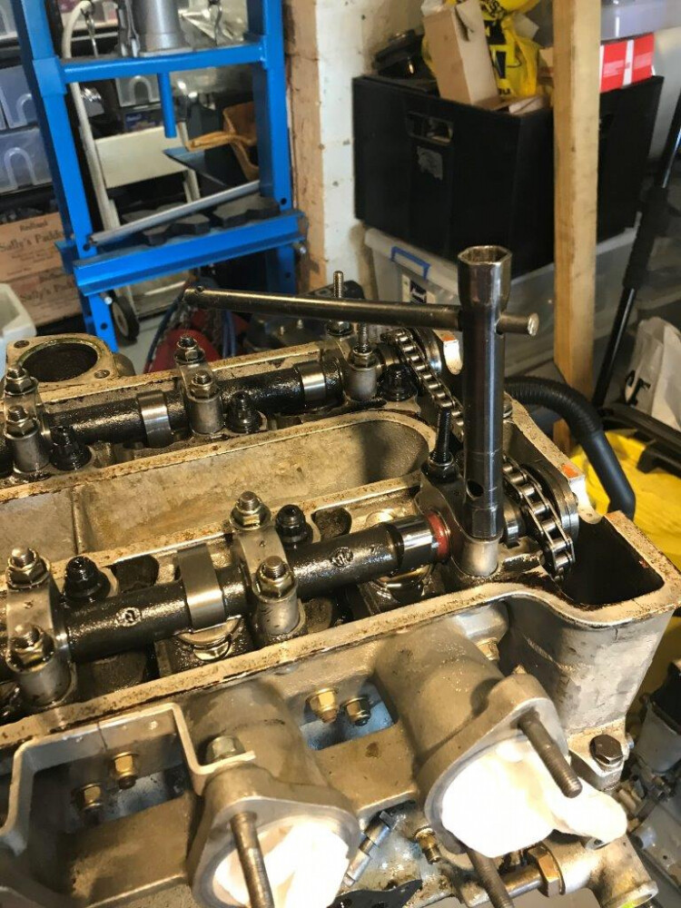
Continuing with the engine dismantling
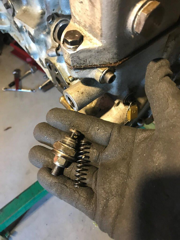
Removing the cam chain adjuster bolt
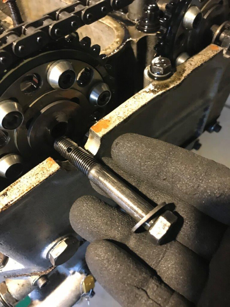
Removing the camshaft sprockets - note the long cam bolt to prevent cam breakages buy putting the front section of the cam from the sprocket to the first bearing under compression from the bolt.
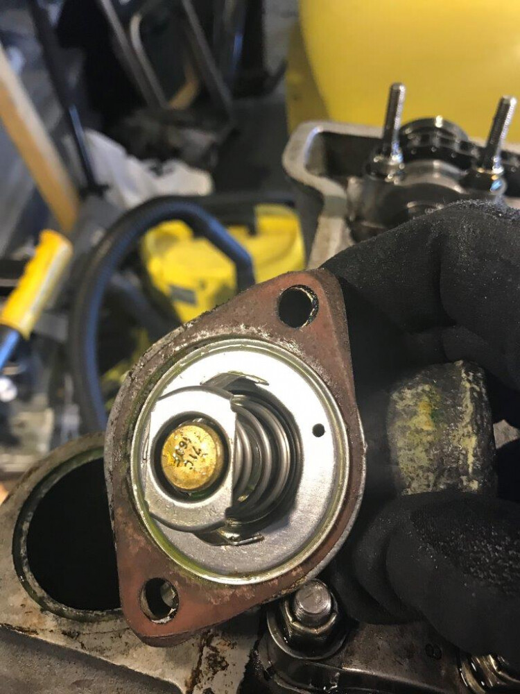
Thermostat housing off - note air bleed hole in thermostat
Removing the cams. Take care to release the bearings evenly a little at a time to allow the cam to be pushed up by the valves that are still open without getting excessive bending stress in the cam by having one end clamped down with the other released and the valve springs pushing up on the free end. I use a tube spanner for quick removal and to reach over the long cam cover retaining studs.
Some cam bearing damage from the metal through the engine but not catastrophic and no damage to cams or cam shaft journals
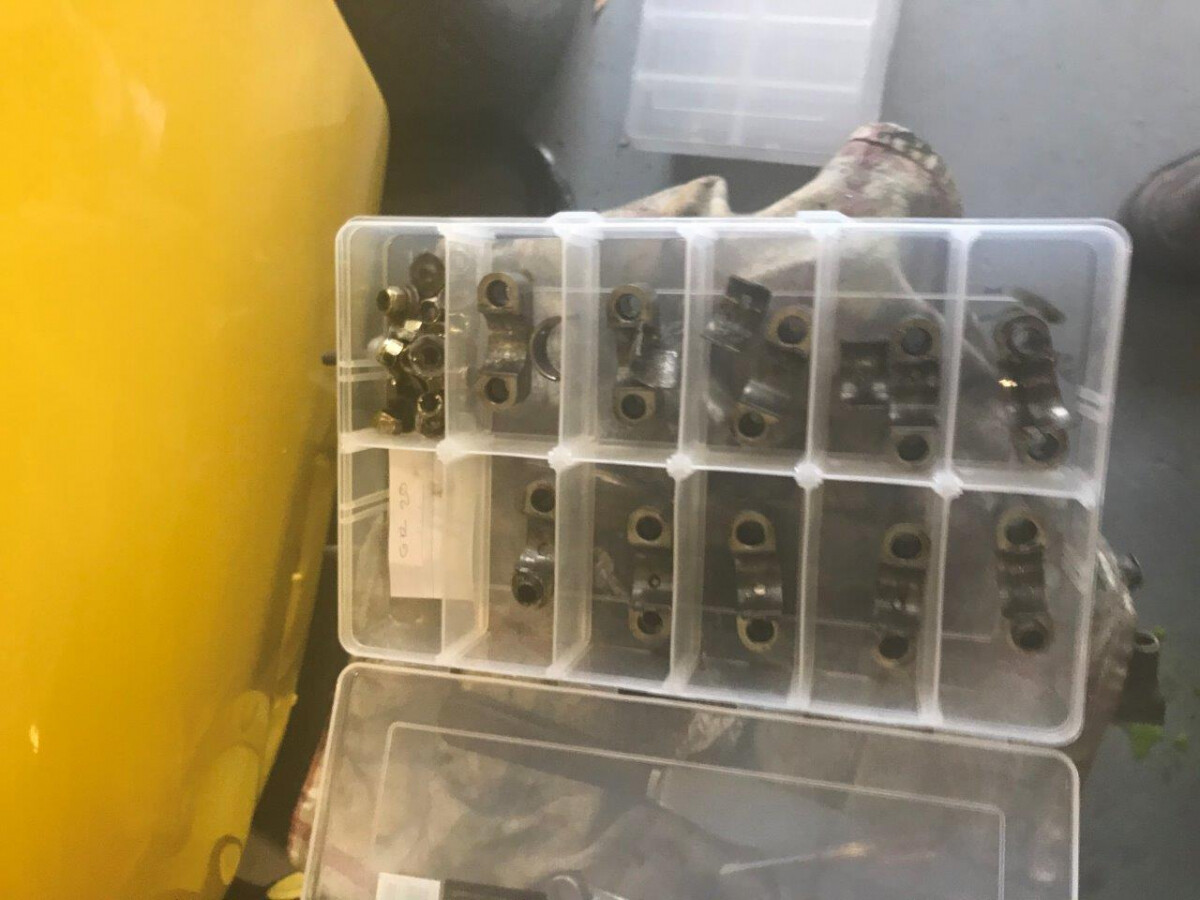
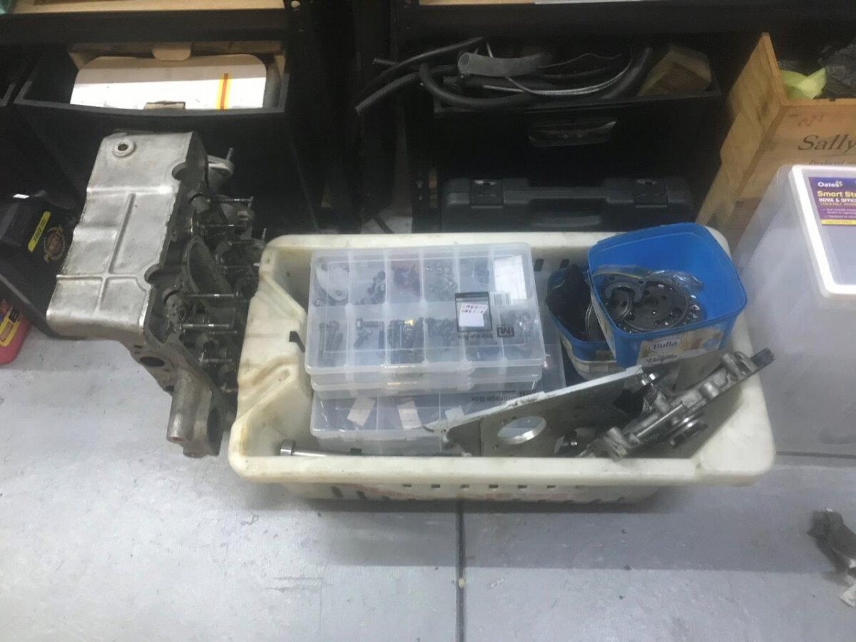
I use a lot of these multi compartment plastic storage boxes. Easy to see whats in them to find parts and easy to keep parts in order so they go back in the same place.
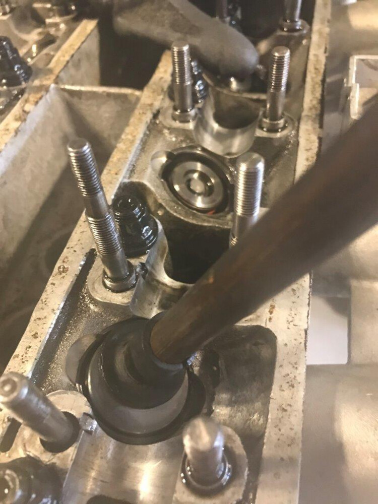
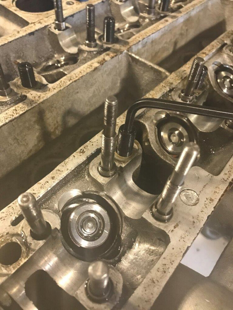
Using a valve grinding sucker stick to remove the cam followers. The shim generally comes out with the follower stuck to the follower shim pad with a film of oil.
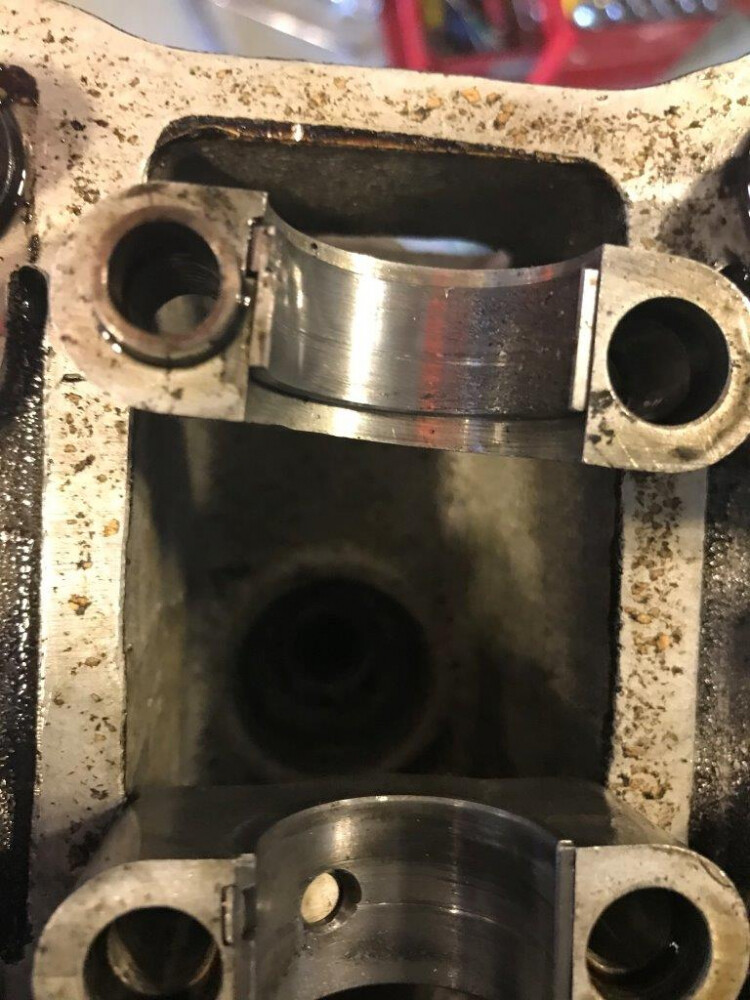
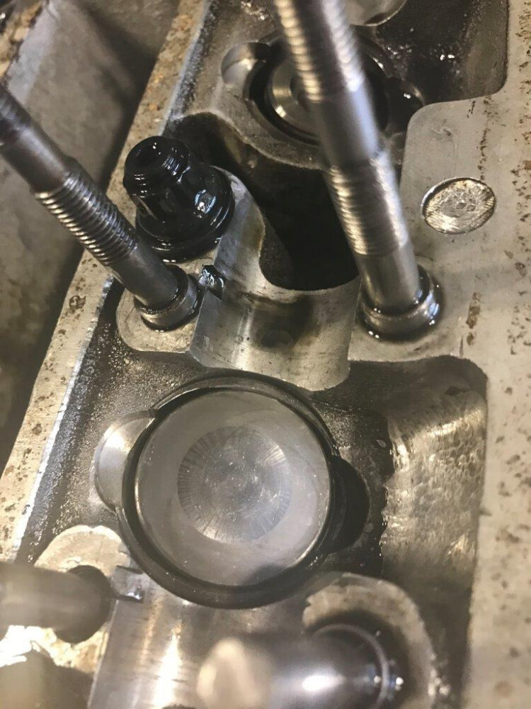
When I got to No4 inlet follower it was rocking in the sleeve bore. You can clearly see the wear in the sleeve at the top as the sleeve wall remaining gets thinner towards the cam sides where it carries sideways load from the cam turning. The wear appears limited to just the top section of the sleeve and the followers are undamaged . High lift cams ( I am using 0.46 inlet) with a small 1.010 base circle can give this problem as the longer follower comes out of the sleeve further than normal putting more load on the sleeve. It appears only one sleeve has suffered this failure but I will need to measure them all carefully once the valves are removed. I will need to think about ways to reduce the risk of this in the future. Another item of machine shop work to be done replacing the sleeves where needed
to be continued …
cheers
Rohan
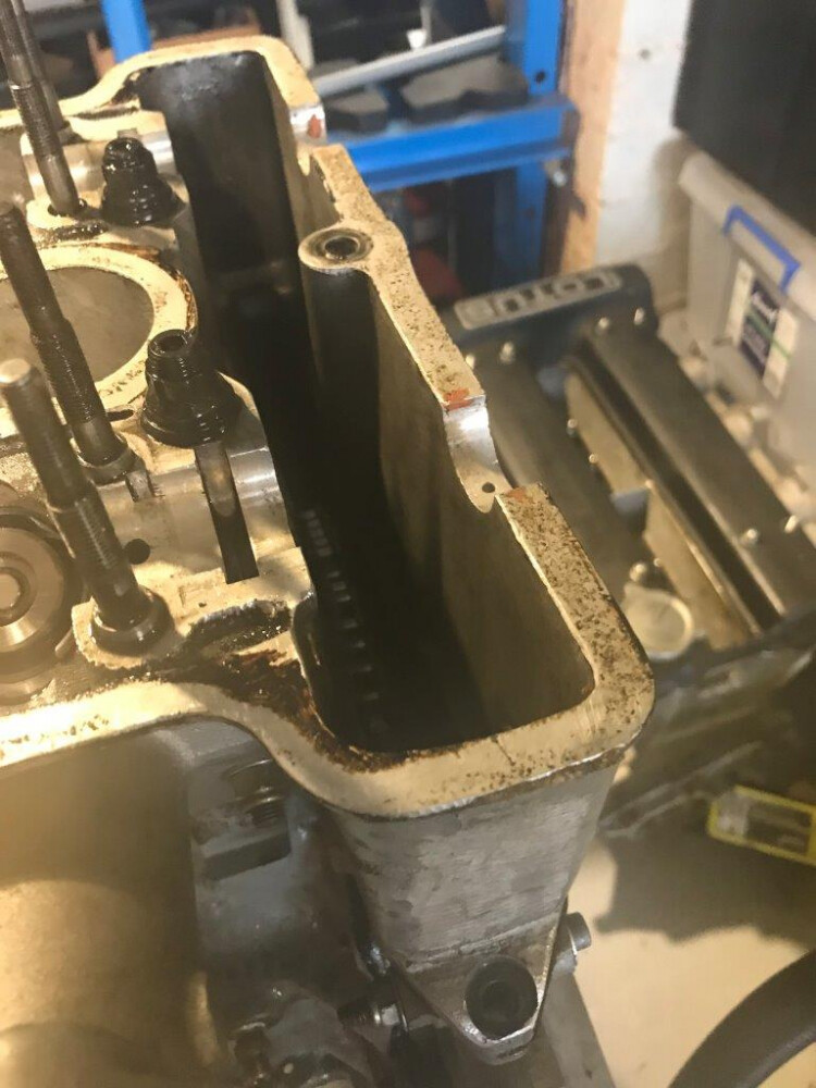
Continuing now with the head removal
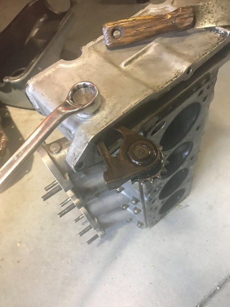
First take of the front 3 bolts to the front timing chain cover
Remove the nuts from the ARP head studs
Remove head studs using the hex socket in their ends. With the studs in place it is extremely hard to remove or replace the head due to the tight hole fit and not perfect location and alignment.
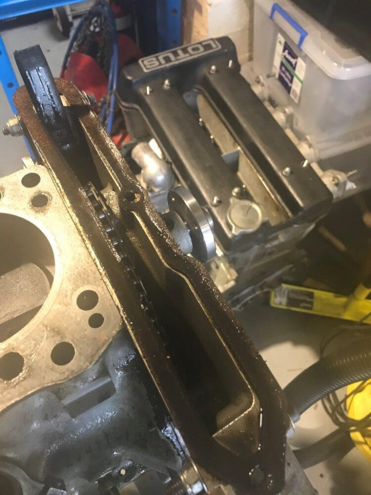
Head of the block and front cover cork gasket was sealing OK and not over compressed
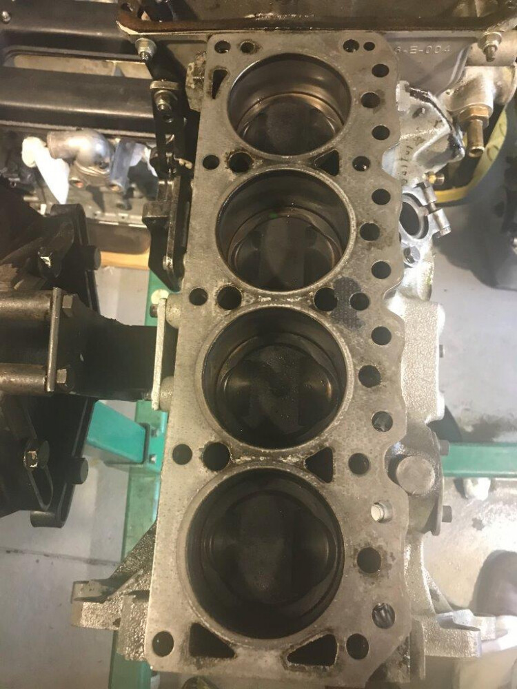
Bores and pistons all look Ok
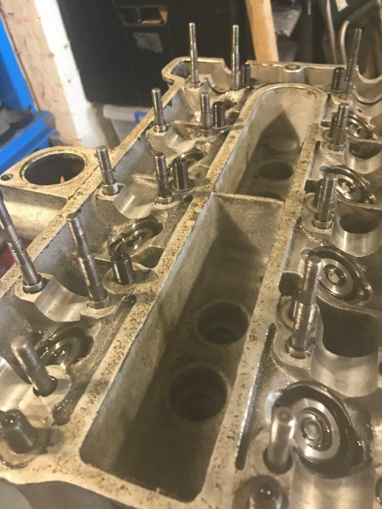
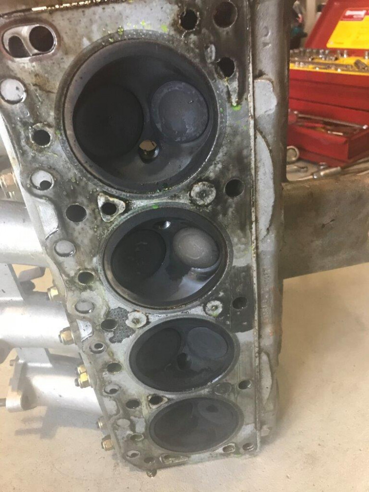
Head looks OK
remove the chain adjusting sprocket and swing arm bolt
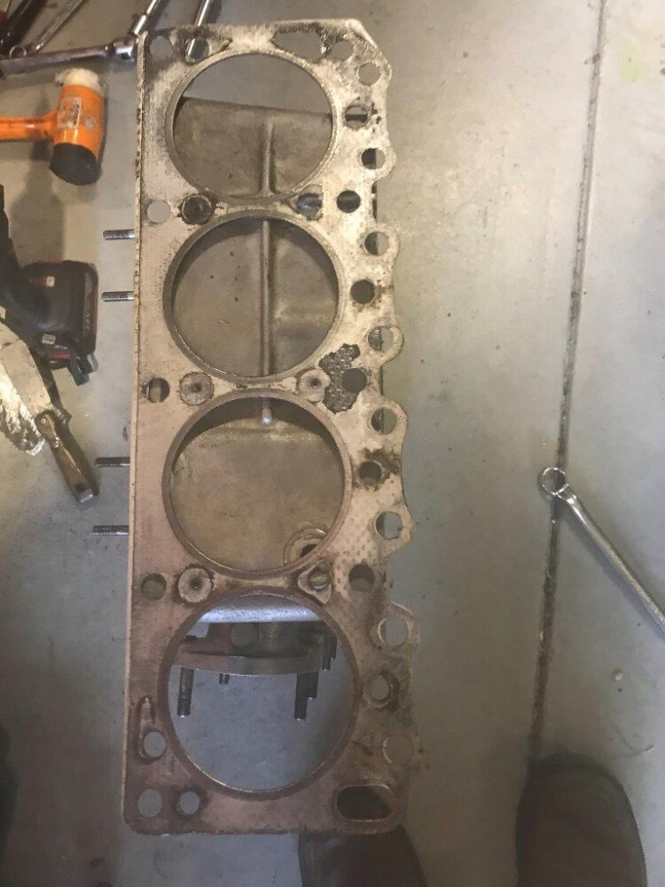
Composite head gasket 85 mm fire ring bore for the 83.5 mm engine bore all looks like it was sealing well with no sign of damage apart from what the removal has caused.
The head with the valves in it will be put aside for later dismantling and more careful inspection and measuring but apart from the damaged No4 inlet follower sleeve all the rest looks good so far.
The dismantling of the block follows in the next episode
cheers
Rohan
Now to continue with the dismantling of the block components.
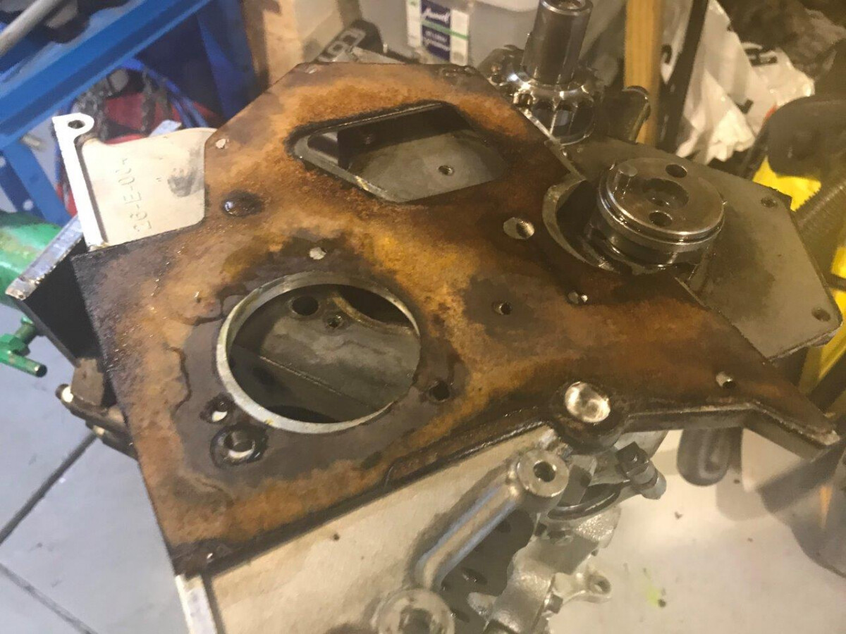
Removed rear crank oil seal carrier
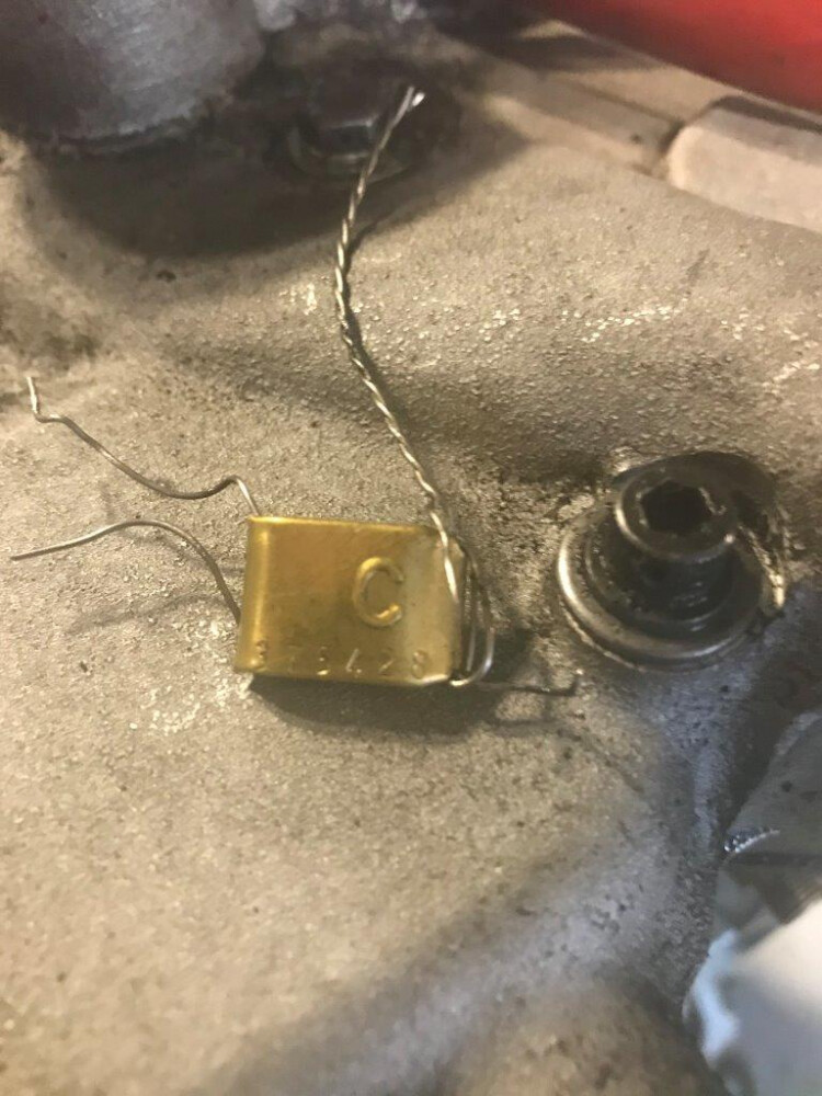
Removal of engine seal. The engine was sealed by attaching a numbered seal through a couple of the bolts on the front cover. This was done by the class eligibility officer when it was built after measuring bore and stroke before the head went on to verify it complies with the rules. I will need to get it resealed once I rebuild the bottom end to this point.
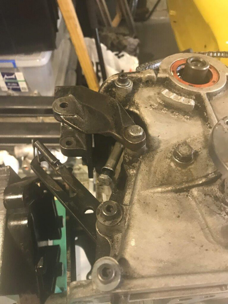
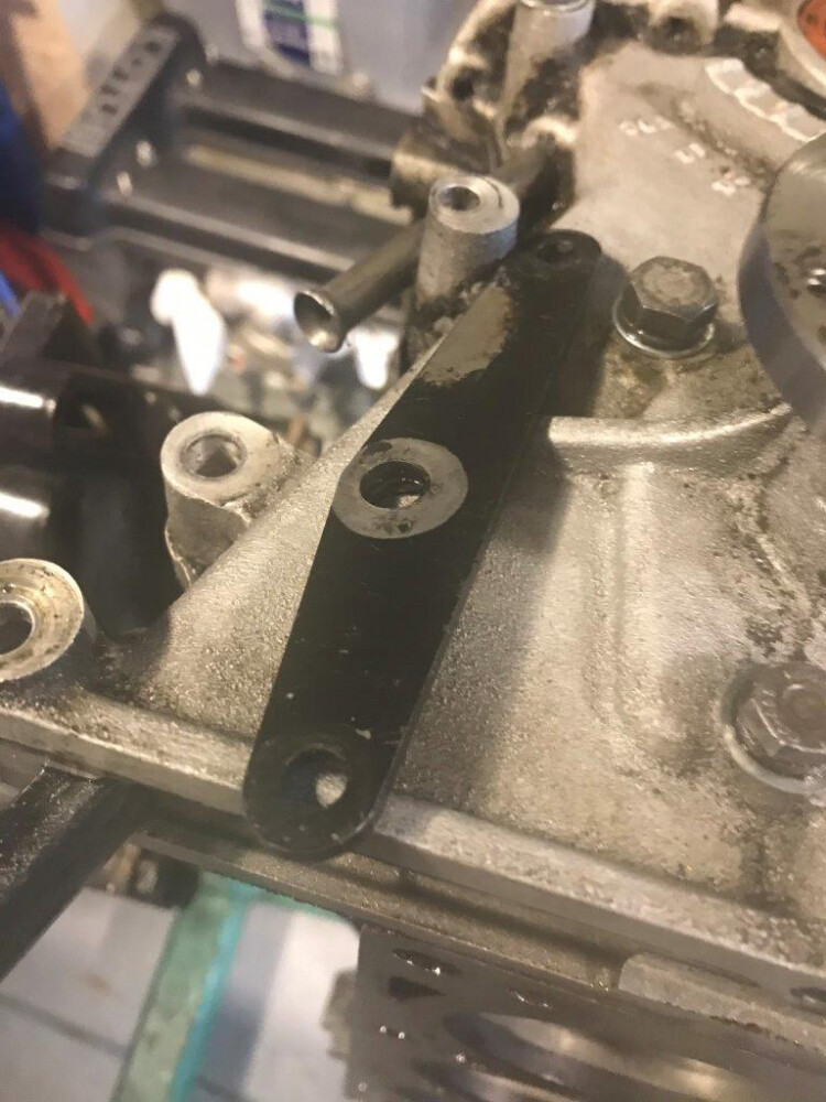
Removed the alternator brackets including triangular reinforcing bracket for where top connection mounts on the front cover. Even with this bracket you can get cracking in the front cover around where the top arm is mounted due to vibration in the nose of the engine at 8500 rpm+
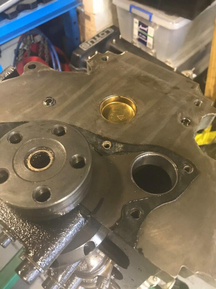
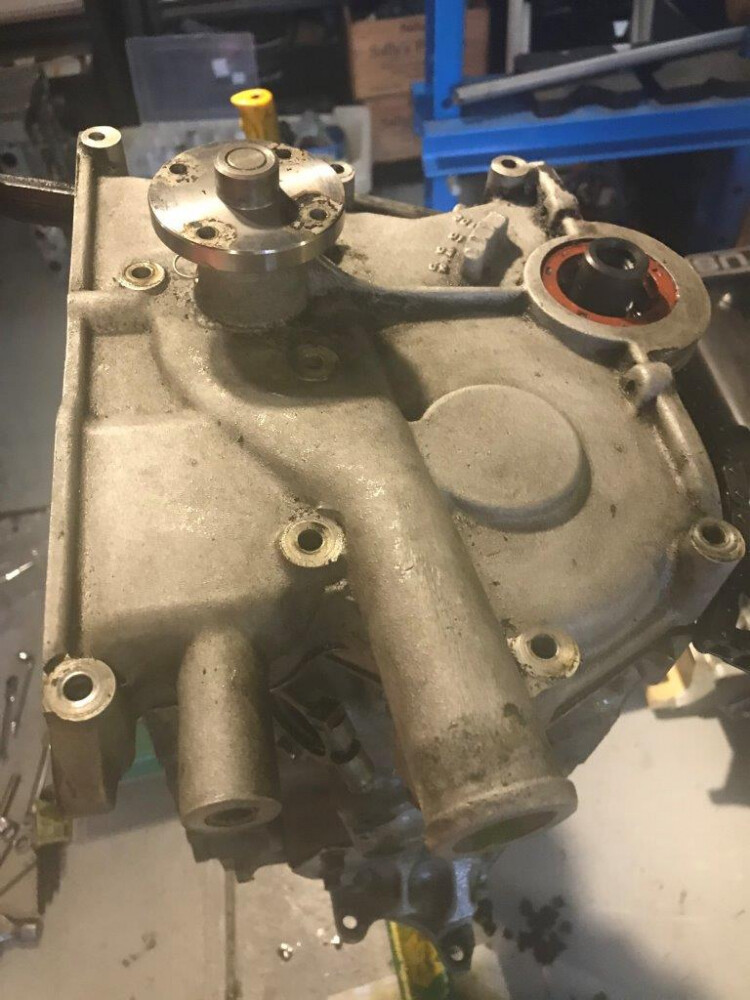
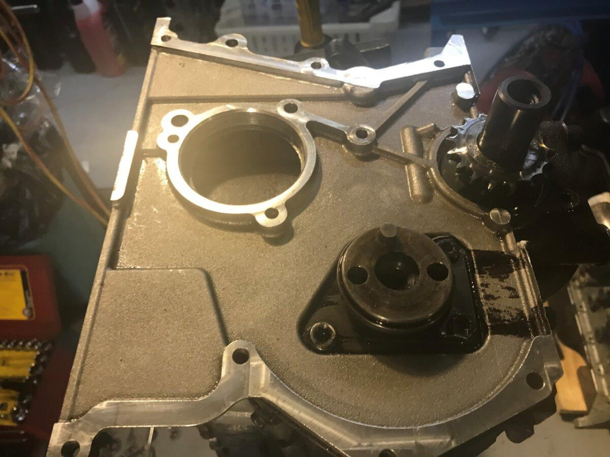
Front cover unbolted and removed from back plate.
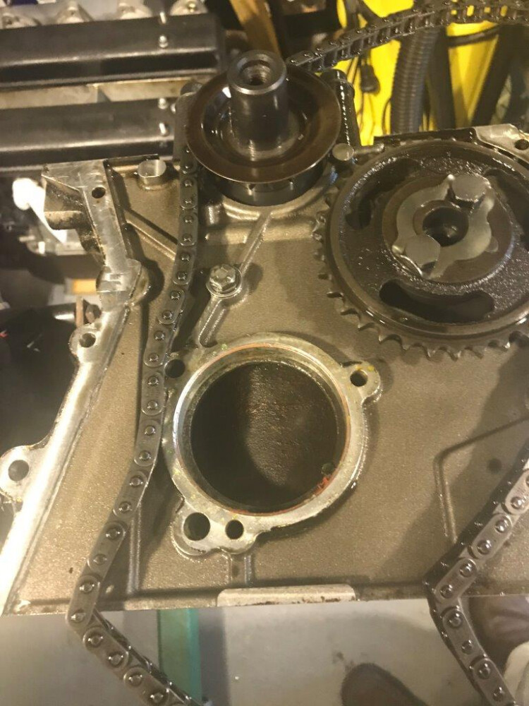
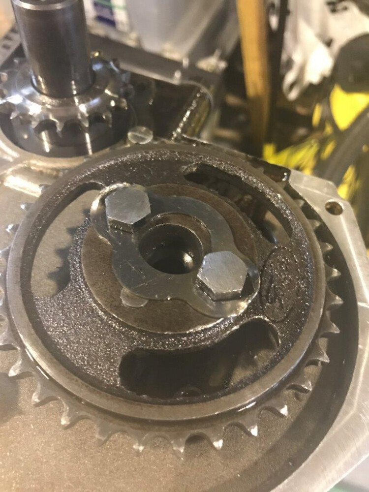
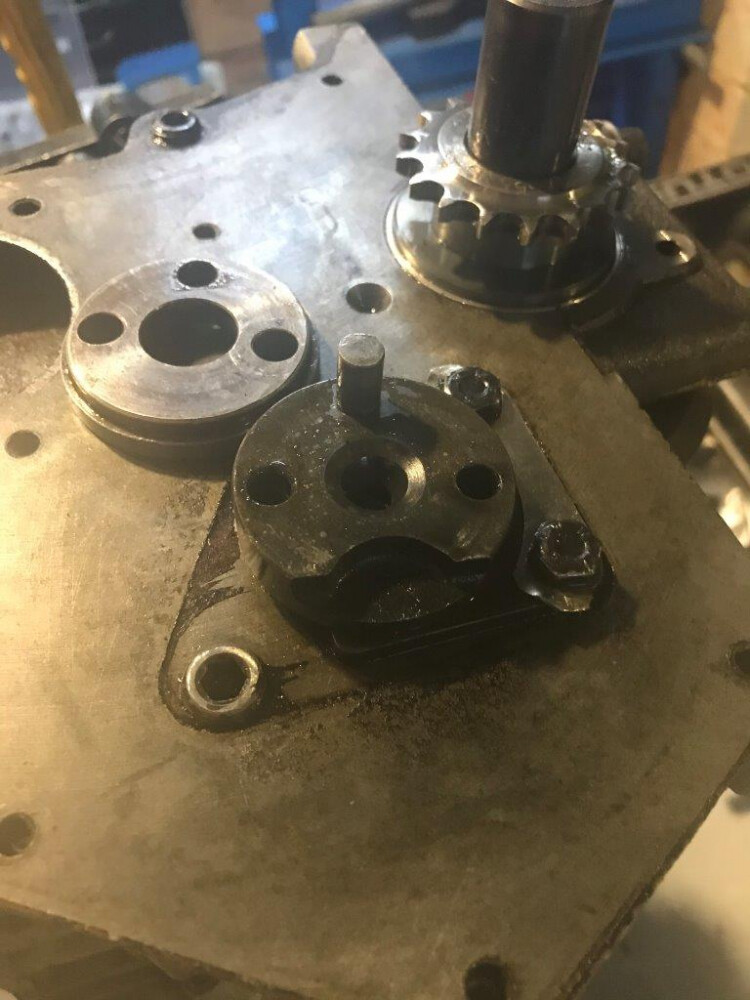
Jack shaft sprocket bolt locking tabs bent down and sprocket removed showing the adapter on the end of the jack shaft. Note I have turned down the heads of these bolts for clearance on the front cover as standard height bolts hit the cover
central bolt on back plate removed so the back plate itself can be removed. Paper gasket between block and backplate sealed using Loctite Aviation Gasket cement as was done with the other cork and paper gaskets. As well as sealing well I find this releases the gaskets with minimum effort for easy cleanup
jack shaft, crank and pistons / rods removal coming up next… I hope I have not bored you to much so far ![]()
Rohan
Continuing with the rest of the block dismantling
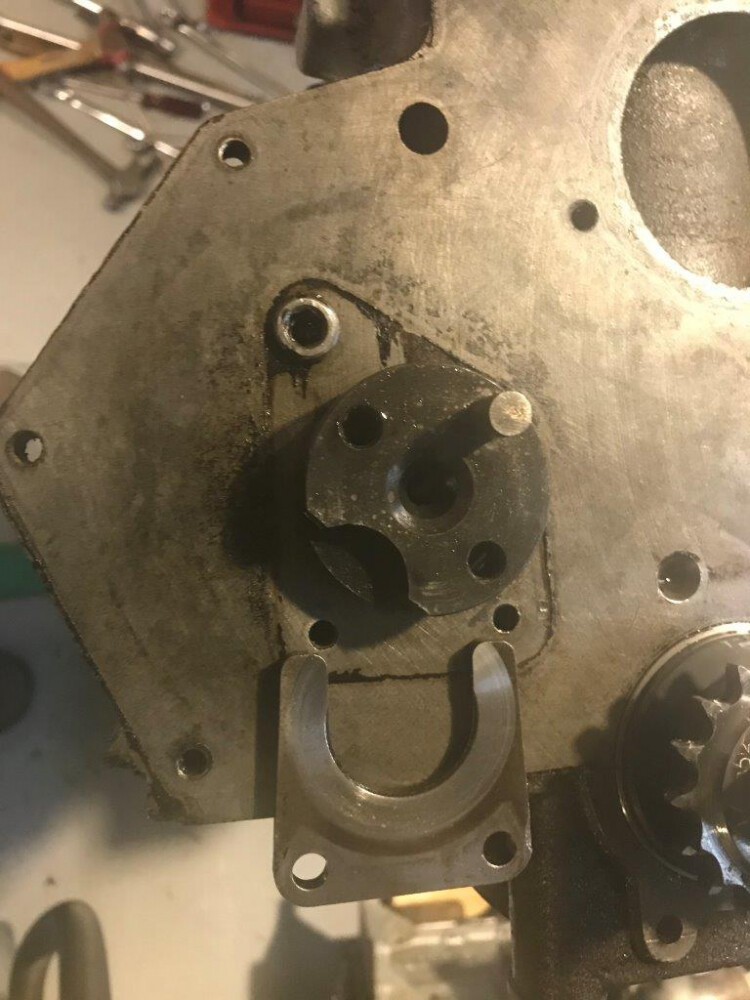
Jack shaft adaptor removed, flatten locking tabs and remove bolts holding jack shaft locating thrust plate.
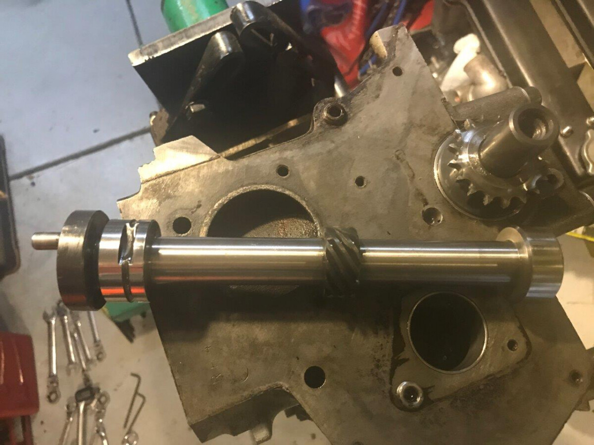
Removed Jack shaft. This is a short steel shaft with no cam lobes and the BDA style single lubrication slot and groove to feed oil to the cam bearings
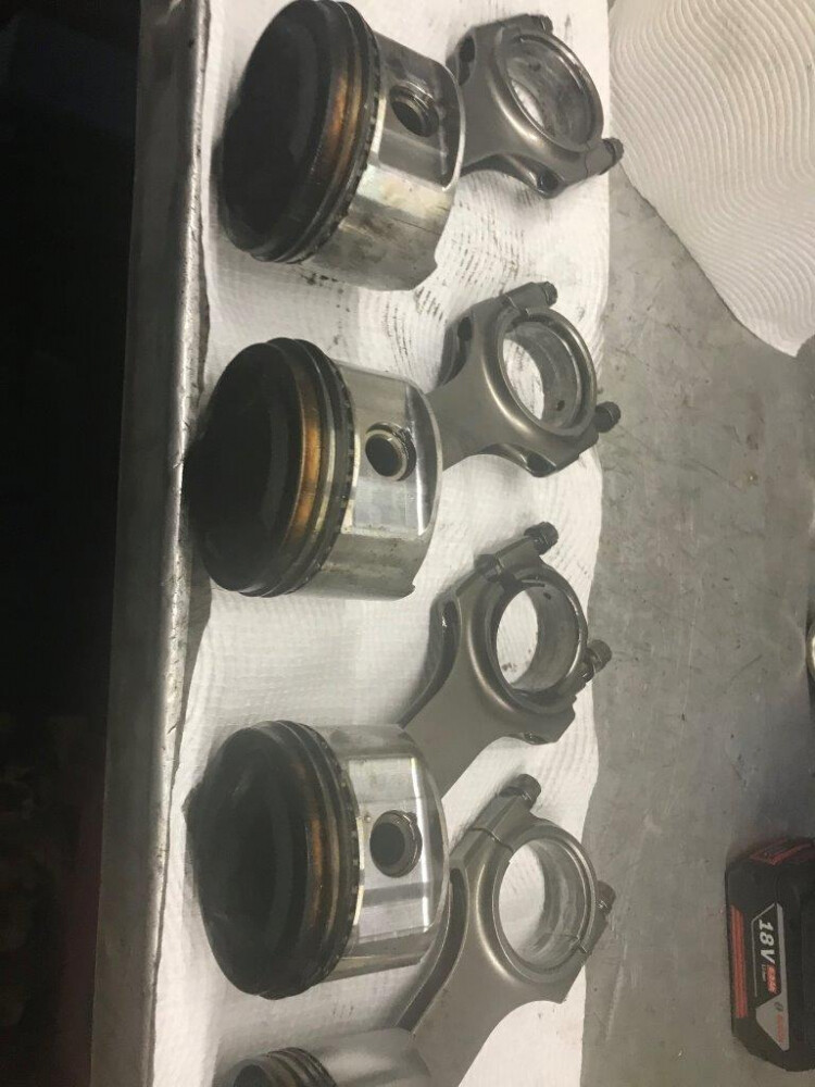
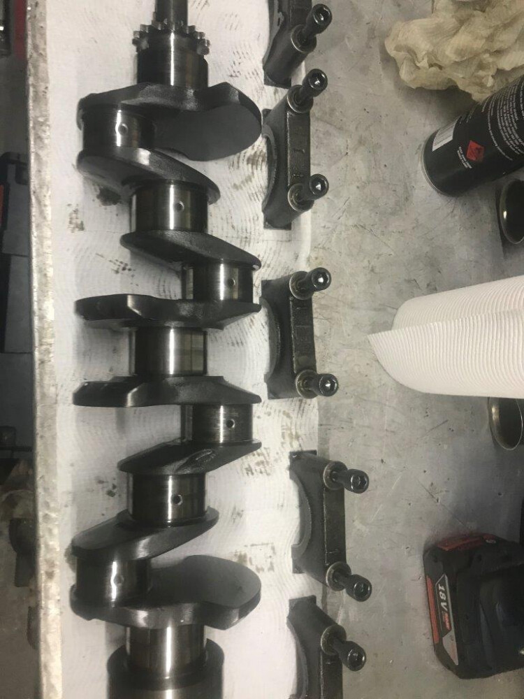
Big end caps removed and pistons and rods tapped out the top of the block. Forged lightweight JE pistons and Carrillo rods.
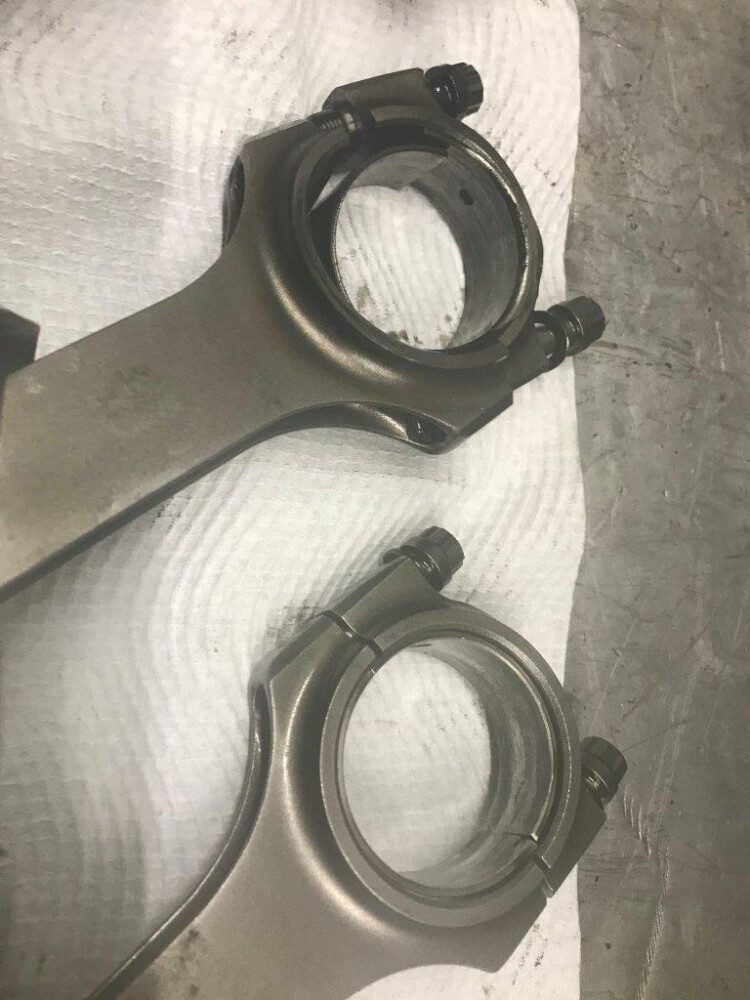
On closer examination the rod big end on No3 piston where the bearing spun is showing signs of a little overheating. See the blueing of the No3 rod near where the rod shank joins the big end compared to the No4 rod next to it. Looks like at least 1 new rod as I would not risk that rod in a race engine . I will check its dimensions and hardness and if OK I may use in a future road engine but in a race engine I would definitely worry even if it tested out OK.
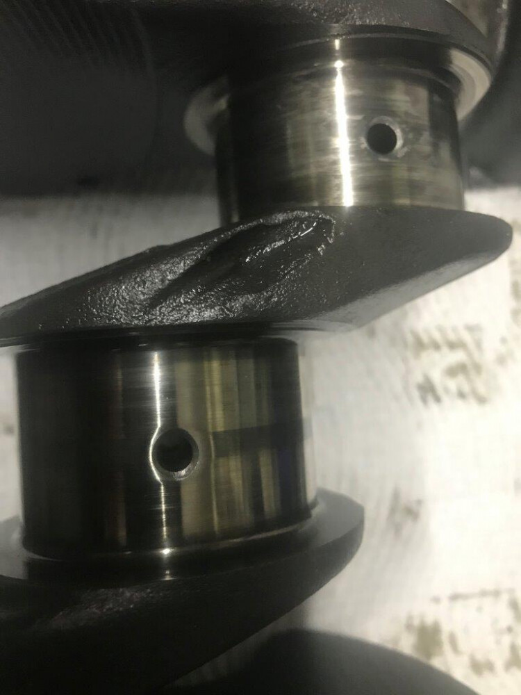
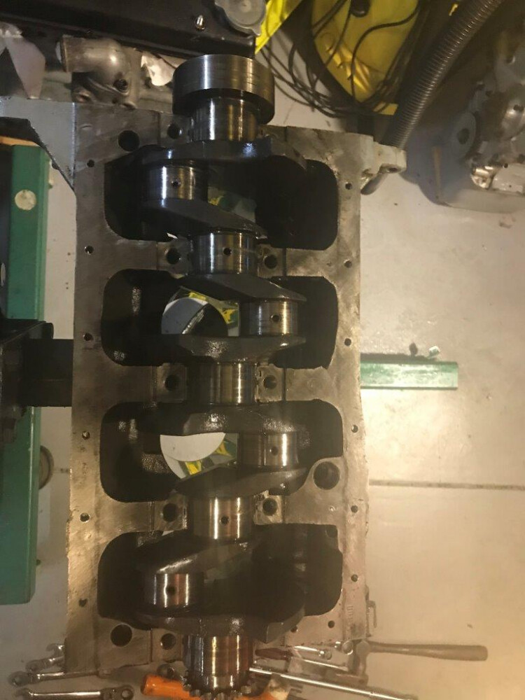
Main bearing caps removed and crank out. Journals look OK except for No3 which will definitely need at least a polish. The crank and rods will be more closely inspected and measured to determine what needs to be done before rebuilding the engine.
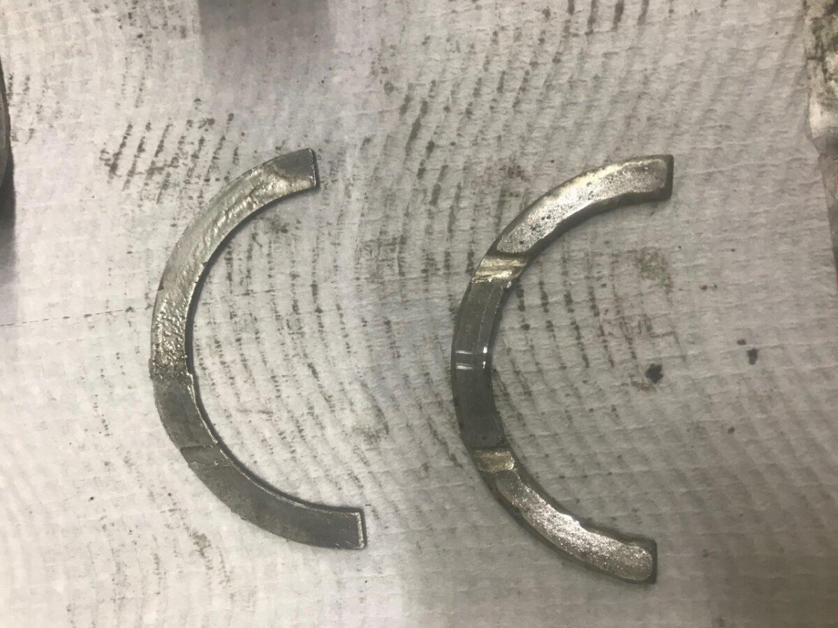
Some damage to the thrust bearings. The clutch (rear) side one has overheated by the look of it maybe due to metal in the oil but also maybe due to sitting on the line at 5000 rpm with the clutch in waiting for the red lights to go out. I have not seen this damage before in my race engines. The front thrust bearing is an over thickness one made to provide the correct clearance with the Datsun L16 crank whose thrust faces are slightly wider apart than the standard ford crank
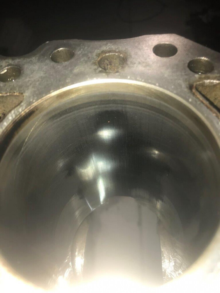
The block bores look good. The polishing of the hone on the thrust face area can be seen in the photo but the home marks can still be seen is this area and more clearly in the rest of the bore. Will carefully check the bore and pistons to ensure they can be reused. This block and piston and crank set has been used 2 times now in race engine builds without re-machining and with any luck they will be good for another rebuild
to be continued…
cheers
Rohan
Well this has finished the dismantling and next steps are cleaning and close inspection and measurement of all components to generate a list of what parts and machine shop work are needed before reassembly.
So far its at least
Polish No 3 conrod crank journal
Replace No 4 inlet valve follower sleeve.
Replace No 3 Carillo rod.
New set of ARP rod bolts ( I always routinely replace them )
A complete new set of bearings including clutch thrust and pilot bearing ( i have)
A new engine gasket set ( I have)
Debating in my head whether I do a routine water pump rebuild as its only 3 years since it was done and it all appears OK.
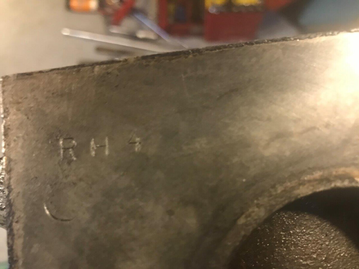
This is my engine block number RH4. I stamp all the blocks that have passed through my hands on the front face so I can keep track of them.
Now is this a “crate engine” as those in the USA would say or is it an engine in a crate ![]()
The cleaning and checking and measuring I will get done in the next couple of weekends. I need to decide whether I rebuild this engine or convert another spare race engine I have to a lower compression ratio to 11:1 to suit 98 Octane unleaded to put back in the car. This spare engine was built with a 12.5 compression ratio for Avgas and it came out of the car 3 years ago when the rules changed banning leaded fuels in historic racing in Australia and the engine that I just dismantled went in.
cheers
Rohan
Are machine shops doing the sort of work you’ll need still open at the moment? I’ve got some motorcycle parts in for repair work caught up in the lockdown here for six weeks now as the business owner has laid off all his staff and shut down his sales counter. He’s doing what he can on his own but everything is backed up. What should have been 10 days is now going to be at least two months.
I will check next weeks if they are open. Most car repair places have stayed open as essential services here so I hope so. Getting work done appears to be quicker than normal as most people not driving plus many people out of work and cant afford repairs so the repair places are looking for work I have been getting quotes for a clutch replacement on my Landcruiser ( after 440000 kms) and people are all offering discounts and can do the job immediately
cheers
Rohan
Are you allowed to use the cartridge front cover modification? It must be quite costly if half way through a season a bearing decides to fail - I cannot imagine it is easy either to get a scrutineer mobilised to cover the vast distances for what might be classed as a routine repair… ![]()
Just looking at the head it appears that #2 Ex valve is a little lighter color than the rest. Would that indicate running leaner or ?
We are allowed to modify internal engine components but must use the original block and head castings. Modification of these components by machining is permitted but not building up by welding except to repair damage. I have used removable cartridge front covers in the past and the eligibility officer has not noticed or objected and as it is a modification by machining and is principally an internal component it is technically allowable at least in my opinion ![]()
When I built this engine back in 2016 / 2017 no one had new cartridge pump front covers in stock but I was promised one in a couple of weeks so I ordered it. It did not come in the time required so I fitted a standard new one that was available within a week ex stock. The cartridge one I ordered was delivered finally about 2 months later after I had finished the engine. I will probably fit this during this rebuild.
cheers
Rohan
It may be a bit leaner. The engine has been set up to run on the rich end of tune for maximum power and minimum risk of burning valves and pistons and theoretically everything is the same in terms of chokes and jets etc so I expect a bit of carbon build up. Maybe a bit more of a carb O-ring leak on number 2 could have caused it to run fractionally leaner but the rest of the plugs, combustion chambers and piston tops even in No2 are all the same colour with the plugs a nice grey / brown tint and black carbon coated on piston tops and combustion chamber
I wiped out the combustion chambers when I removed the head to get rid of oil and water that gets in when you first lift the head off. Wiping removed the loose carbon off No 2 exhaust valve and revealed the light deposits you see underneath when it did not on the other combustion chambers. When i clean up the head I expect I will see similar light brown / grey deposits on the face of all the exhaust valves under the soft carbon coating on the surface
cheers
Rohan
Rohan if you are looking for more lubrication at the rear thrust washer would your race series allow this small mod (I don’t think it can hurt not to do it if I’m honest) to the centre main bearing housing? :
If you are using custom made thrust washers is there no way of copper or bronze ones being made as those you have look to be silicon alloy (in colour at least)? Lead copper etc is good at accepting particles into the material and keeping it away from the metal surface it runs against. Silicon alloy seems a bit hard for this.
Could you also modify the block to accept full compliment thrust washers like the new Ford blocks do? Tuners used to use Pinto (if I remember correctly) thrust washers in Twincams etc at one time to give the same effect. They have tabs on them to stop them spinning in the block.