As car was completely stripped can anyone tell me which holes in the chassis are for fuelpipe.brake line etc. Itake it that handbrake cable fits to low left hand hole as viewed from front to rear .

Some photos of my uncompleted S2 Elan, this should help you with the fuel line and E brake line. hope someone comes along and give you some better photos.
Gary

The brake bundy pipe is on the inside of the right front chassis fork and goes under the spine of the chassis backbone and comes up through a grommet and hole in the bottom of the spine near the rear bulkhead of the chassis. I would have gotten a photos of that but its raining and melting away all of that nasty white stuff we recieved on the 3rd of this month. The hole is just large enough to fit the bundy nipple through, around 1/2 to 5/8 of an inch.


Thanks Gary the photos are a great help.Hope the white stuff melts for you as we bask in the mid 20s- trying to get some paint on body while its still warm.
Graham
Graham,
Gary’s photos give you the correct information regarding the fuel line and handbrake cable, but I suspect they are of an Elan chassis rather that a +2. The hydraulic line to the rear brakes does not duck under the front bulkhead of the tunnel section as shown in Gary’s photos. On the +2 the hydraulic line goes through this bulkhead via the lowermost, left hole (as seen in your photo). The tabs welded to the chassis to locate the hydraulic lines point you in this direction. The handbrake cable housing on a +2 is screwed into a threaded fitting in the chassis (3/8-24 UNF?) and this is part of the handbrake adjustment. These fittings are in the same locations that Gary shows so there should be no confusion here. These are among the small, detail differences between the Elan and +2 chassis.
In Gary’s first picture I think you can see the handbrake cable going through a hole in the in left of the chassis “diaphragm”. If I recall correctly, on a RHD car it should go through the right hand hole and the equivalent hole in the second diaphragm - in fact if you look where Gary has put the RHD sign you can see the second cable hole towards the rear of the chassis. I’m not sure if this is the case with a LHD car (I guess it depends if they change the handbrake tree to suit the side the driver sits on). There is also a small tube across the chassis - I think the cable goes below this. On the basis that Gary’s car is LHD, and Lotus used the same handbrake tree regardless, I suspect that the cable on a LHD car goes in the front hole as shown in Gary’s picture but then should actually go under the cross pipe and through the left hole at the rear (i.e. it crosses from one side of the tunnel to the other). As shown in the picture the cable is v.likely to foul on the prop-shaft/drive shaft.
These (esp the rearmost hole ![]() ) are a bu**er to find when the diff and suspension is in the car - requiring a mirror, handy light and the dexterity of an octopus!
) are a bu**er to find when the diff and suspension is in the car - requiring a mirror, handy light and the dexterity of an octopus!
…and if anyone’s managed to read this post without sniggering you win the “pure of thought and mind” award 2010!
Craig
The photos are of a late October 1965 S2 26/4997, a LHD U.S. delivered roadster that was driven from 1966 to 1969 when it was taken off the road due to some sort of problem with the Cylinder head. The mileage was in the high 30k range and I do not believe that it has ever been apart before other than the head was in the boot when I bought it. I use this chassis a lot for photos because no one has messed about with it including (especially?) myself. Graham asked a question and there were not any responses when I looked at 3am. I had one of the photos from when Ed was having problems with his handbrake routing issue and the other two were taken early this morning. I didn’t put a lot of description in the topic other that to say they were of MY S2, then again Graham didn’t specify much either but at least he’s got a location filled out in his profile.
So getting to the subject of LHD - RHD cable runs, they both go through the front guide holes, at the rear of a LHD Elan, it goes over the seat belt threaded tube and uses it as a guide of sorts. As for the RHD I can’t say but it would appear that it would go through the rear bulkhead cable guide hole on the right hand side of the Elan (looking rearward the left, bottom). As far as putting e-brake cables in chassis, I buy new ones and have not had any issues with them (but I only use it once a year anyway for the annual inspection). They get installed FIRST on a bare chassis along with the fuel line and rear brake pipe. These parts are always NEW parts as it sucks to go back to this location to do any job a second time.
I am not sure why I am answering posts on plus2’s as I sold mine before I did much to it, If I had done any more it probably would have been a parts car which was reason I bought it in the first place. It was the nicest looking parts car I had ever bought. I new I had screwed up buying it site unseen as it was way to nice for me to own, so I sold it to a good friend that wanted a nice project car from Florida. Any way I thought a couple of photos may help Graham but I guess I was wrong (again) and I confused the issue by posting something that I thought would be a common design. I new that if I was wrong that someone would correct me and probably sooner than waiting for someone else to post a photo or two of a plus2 backbone spine.
So there you go, the rain stopped and only turned to flurries at the end of the storm so its mostly bare ground here. My guess is that 30 miles to the north its still very much white all over…
Gary - apologies if I came across as being critical, it’s really helpful to see the pictures of the chassis you’ve posted. I don’t have any to hand and it’s great that you’ve taken the time and effort.
The reason for my response was that on my RHD +2 I once fitted a handbrake/ebrake cable through the front RH hole, missed the hole in the rear diaphragm and threaded it through the large propshaft/driveshaft hole at the rear as it does in your picture. It caught on the propshaft and damaged the cable. Given the weakness of the handbrake on Elans I think I’d have had to be very unlucky for it to have caused an accident but you never know… It was only when replacing the cable and was cursing the designers that I noticed the second hole in the rear diaphragm and realised I’d got it wrong. It then seems logical that the cable should run in a straight line between the two (i.e. under the seat belt tube), although in this latter assumption I accept I could be wrong.
I’d presumed that this arrangement should be common to both the two seat and the 2+2 but have no experience of the two seater so am more than happy to stand corrected - although Brian Buckland’s book on the 2 seater he does say “…there are 2 holes in the spine that the cable has to go through. The front entry one is easy but the exit one in the rear diaphragm can be difficult. I use a long 3/8 diam. dowel rod with the cable taped to it about 2 inches overhanging. The tape will break off when you can pull the cable through the hole.” which implies to me that it runs the same way as on the +2.
Thankfully our snow (at least temporarily) disappeared at the weekend and a quick battery charge and some fuel meant I got to enjoy the +2 in the sun ![]()
C
My running 65 S2 Elan, had a new fuel line but it dropped onto the spinning propshaft and cut through it. replaced and gravity won’t win this time

yet to run 70 Coupe, all nice, clean, and red

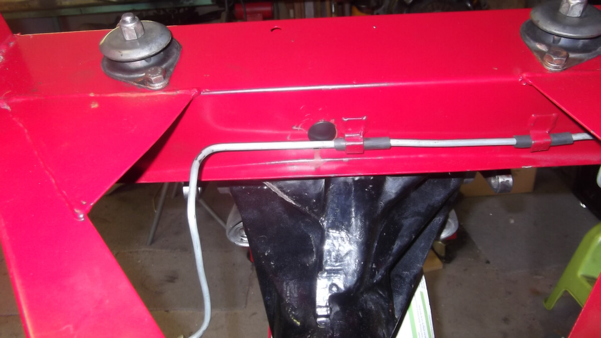
yet to be assembled Spyder chassis, just the new brake cable and brake bundy line installed

Hi Craig
wrong again. I shouldn’t answer questions without doing the research. On all three the e brake line goes through the front and rear guide tubes and under the seat belt threaded tube. Thanks for pointing out the errors, I don’t like being wrong but I hate leaving information wrong even more.
Gary
p.s. bet ya’ll think I like Spyder chassis?
I am a moron once again, this time with help from Lotus. I finally checked my +2 chassis when I got home tonight. I should have done that before going off half-cocked and posting my comment this morning. As far as I can tell, Gary was entirely correct with regard to the handbrake cable routing. I mentioned the threaded fitting in the chassis for locating the handbrake cable housing. This is in the engine mount bracket, not the tunnel bulkhead as I had postulated. There is one in each engine mount bracket for LHD and RHD applications. The new stuff, to classify me as a moron, is a change in the chassis with respect to the rear brake hydraulic line. This evening I re-checked my original chassis and found that I was correct in stating that the hydraulic line passes through the low, left-side hole in the bulkhead. In my replacement chassis this locating fixture is gone and the rear hydraulic line must duck under the bulkhead as is shown in Gary’s photos. When I feel better I’ll challenge the bolt tightening discussion at “Things in Common”.
Thans for the replies- I didnt think that it would be so confusing -Maybe I havnt engulfed the Lotus culture yet with its apparent differences between cars.
Graham
Gary - thanks for checking! Good photos, just goes to show you can never have too many projects (and someone’s going to get lucky if you ever sell any of them on)…
Craig
Hello,
it is really unfortunate that the pictures that Gary posted in Jan 2010 are not here anymore. I am rebuilding my Plus2 in a “new” original chassis (and getting rid of the 1985 Spyder chassis). But I did not pay attention to how the handbrake cable goes though the chassis main beam. Not sure that what I could have documented from the Spyder setup would be relevant anyway. In addition on hte Spyder chassis the (solid copper) fuel line was routed ouside the chassis and body which is not the way it’s done on the original chassis I suppose.
So I’d love to know where the fuel line goes in the main beam (where it enters the rear of the main beam and where it gets out). I have noticed there are two holes about 12mm in diameter at the top right corners of the main beam bulkheads. Are these for the fuel line ?
I’d rally like to know also where the handbrake cable goes into the main beam and how it is routed at the exit. Looking from the back, it seems the cable cannot go straight through the main beam to the pivot asembly at the back. I really wonder how it is laid out.
Thanks in advance for your help
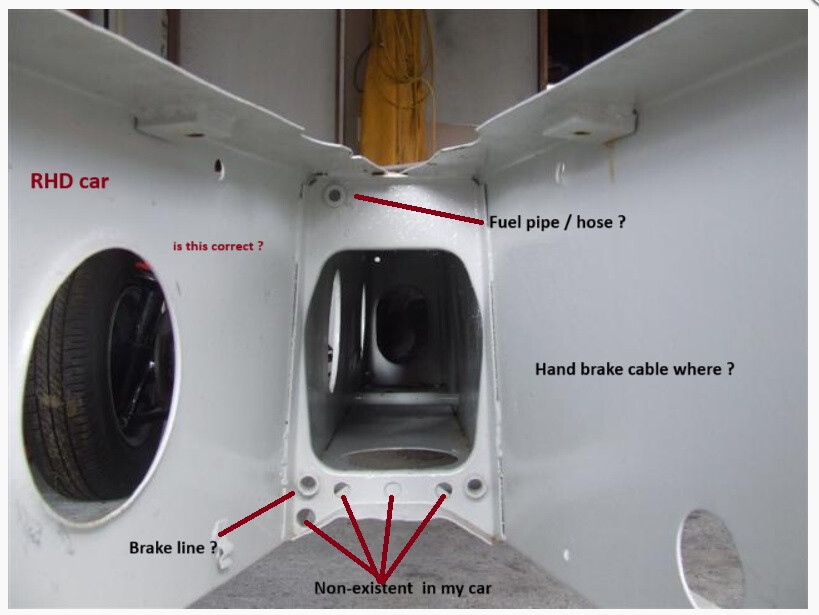
Top left as you look is fuel line, as identified.
Bottom Left “non exisistant” is brake hydraulic line. As it run on underside of the chassis not in the tunnel.
The handbrake cable goes through the one marked as “brake line ?” on RHD cars, or the opposite side on LHD. For LHD it runs diagonal through the back bone. RHD stay down the same side.
Thank you that really helps ![]()
I guess I will have to withdraw my hydraulic brake line from this hole at the bottom left and replace it with the handbrake cable. And do the same at the back end of the main beam. Then, I will try to drill holes in the front and back blukheads to install the hydraulic brake line. Indeed, as you can see, the chassis has been stiffened as per lotuselan.net/wiki/Chassis_Modifications, and there is no way the brake line can be installed underneath the chassis. Let’s hope my drill can reach there and I don’t have to pull the diff and the motor+g’box to do it.
Thanks again
Francois


Thank you Brian
Nice photographic record !
When I have drilled new holes for my hydraulic brake line I will also but rubber grommets.
For the fuel I have a stainless steel braided hose and It does not fit in the bulkhead holes by 2mm. I’ll try to enlarge them. If that does not work, I’ll drive it through the big one.
Have a great day
Francois
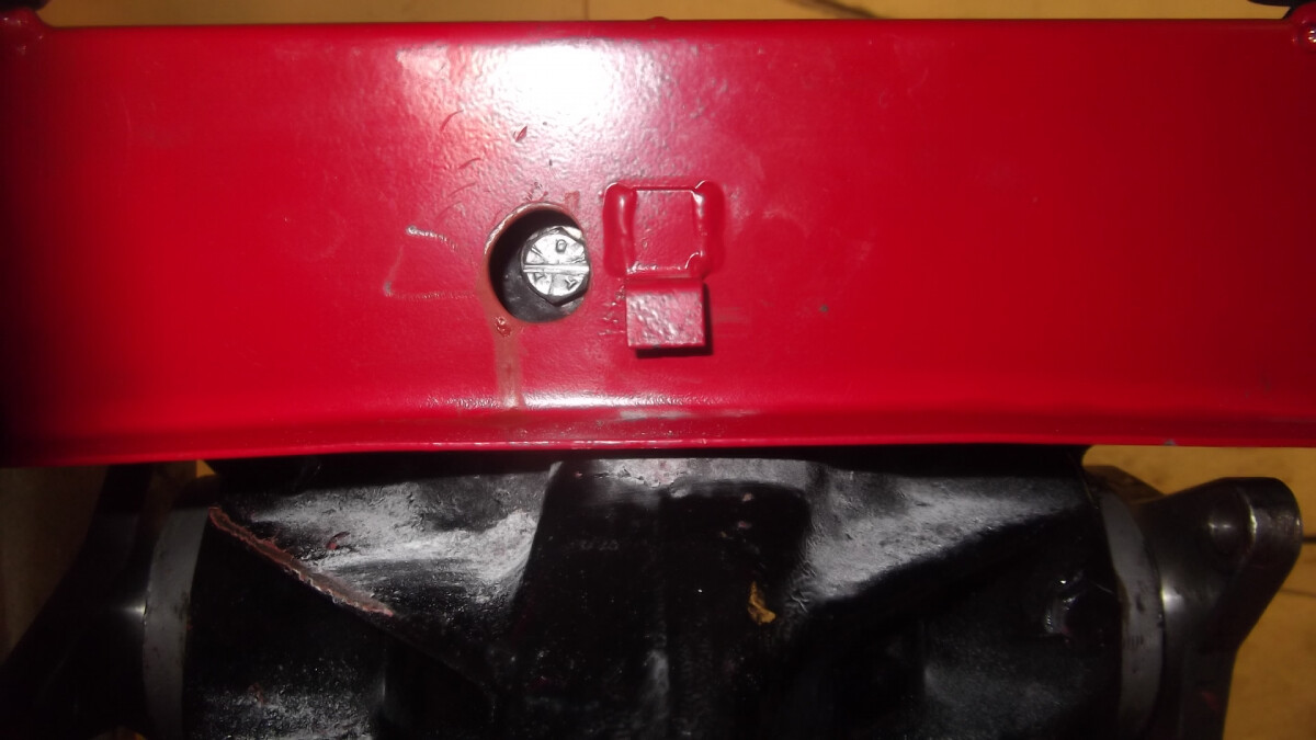
It is difficult when fitting/removing a Sprint type diff brace (with the body on) to locate and tighten the centre bolt so I modified my chassis to make it easier. I drilled a hole to correspond with the bolt to enable a socket to be used.


Hi Brian,
I must say that I fought with the diff twice to remove it from the chassis and put it back in with the body in place. But I never thought about parting the two halfs (front cone with gearing and back housing) with the diff on the chassis. Can you tell me the reason to do it ? Is it quicker if you have to change the gear ratio at the track ?
Best regards
Francois
Francois,
The mod is not for separating the diff from the housing, its just for getting the complete diff in and out.
If you have the strengthing diff brace fitted then it is difficult as the brace has to be removed first. The hole allows you to get to the bolt that secures the brace to the diff.
Hope this makes sense to you.