I have seen a couple of cars with gauges in the engine bay. While I can understand the need for a gauge when setting the pressure, I don’t understand the ongoing need for a gauge unless the pressure regulator is no good and wanders off. The bourdon tube for a low pressure gauge is going to be very thin, and I would have thought a bit of a fire risk if it breaks and starts to leak.
I used a Vibrant transition from 4” to 3” diameter, and a second transition in the nose to fit to the air filter housing. I think this is the one. It needed a bit of trimming for length
Looks like they also make a 4” x 3 1/2” 45 degree version as well if that is your trunking size
https://www.summitracing.com/parts/vpe-19773
HTH
1 Like
Agree with that, keep it as simple as possible.
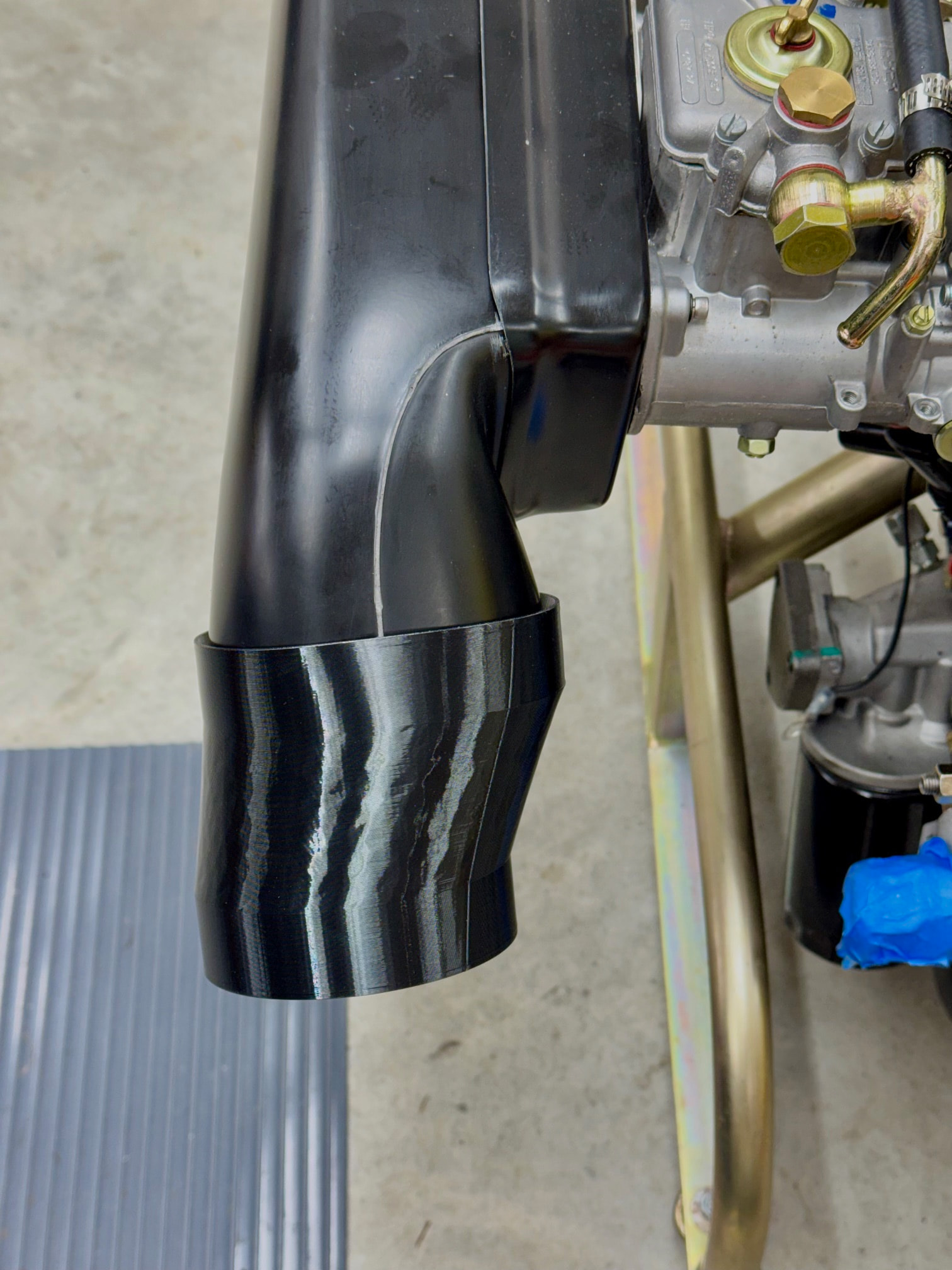
Thanks @stugilmour , I had looked at those, but I’m not sure they will fit without rubbing due to the offset needed to clear the radiator bracket. I printed this test out of TPU yesterday just to see how well it would fit the airbox. It seems fine and will offer an airtight seal with a clamp. The final version will need the transition area shortened and the offset possibly increased but I’ll need the engine back in the car to do that work.
I looked at a photo taken of the Sprint I visited last week, and it appears that the factory airbox nozzle is positioned in essentially the same position as my airbox. I’ll need to visit the car again (heads up Jeff E ![]() ) to be certain and take a few measurements, but if it is, then there may be something a little off with my radiator bracket.
) to be certain and take a few measurements, but if it is, then there may be something a little off with my radiator bracket.
Regarding a permanently mounted fuel pressure gauge, that’s not in my plans. If it turns out I do need a regulator, then I’ll simply install an inline T-fitting and swap the plug for the gauge when needed.
Very trick! Looks perfect. I had to fettle the Vibrant piece a bit. Looking good.
Another update with limited progress. FedEx has misplaced my package from QED with the trigger wheel and CPS bracket after it cleared customs 2-1/2 weeks ago. I’m hoping for resolution this week but suspect it will involve a new order. The flywheel is still on backorder. The update I was promised to receive last week never materialized. Hopefully I’ll have an answer in the next few days. The clutch and pressure plate, along with a few other parts, are also still on backorder, but those items look to ship soon. Lastly on the known — and this time self-inflicted — delays front, I forgot to order the AEM wide band O2 sensor a few weeks ago. That is scheduled to arrive tomorrow.
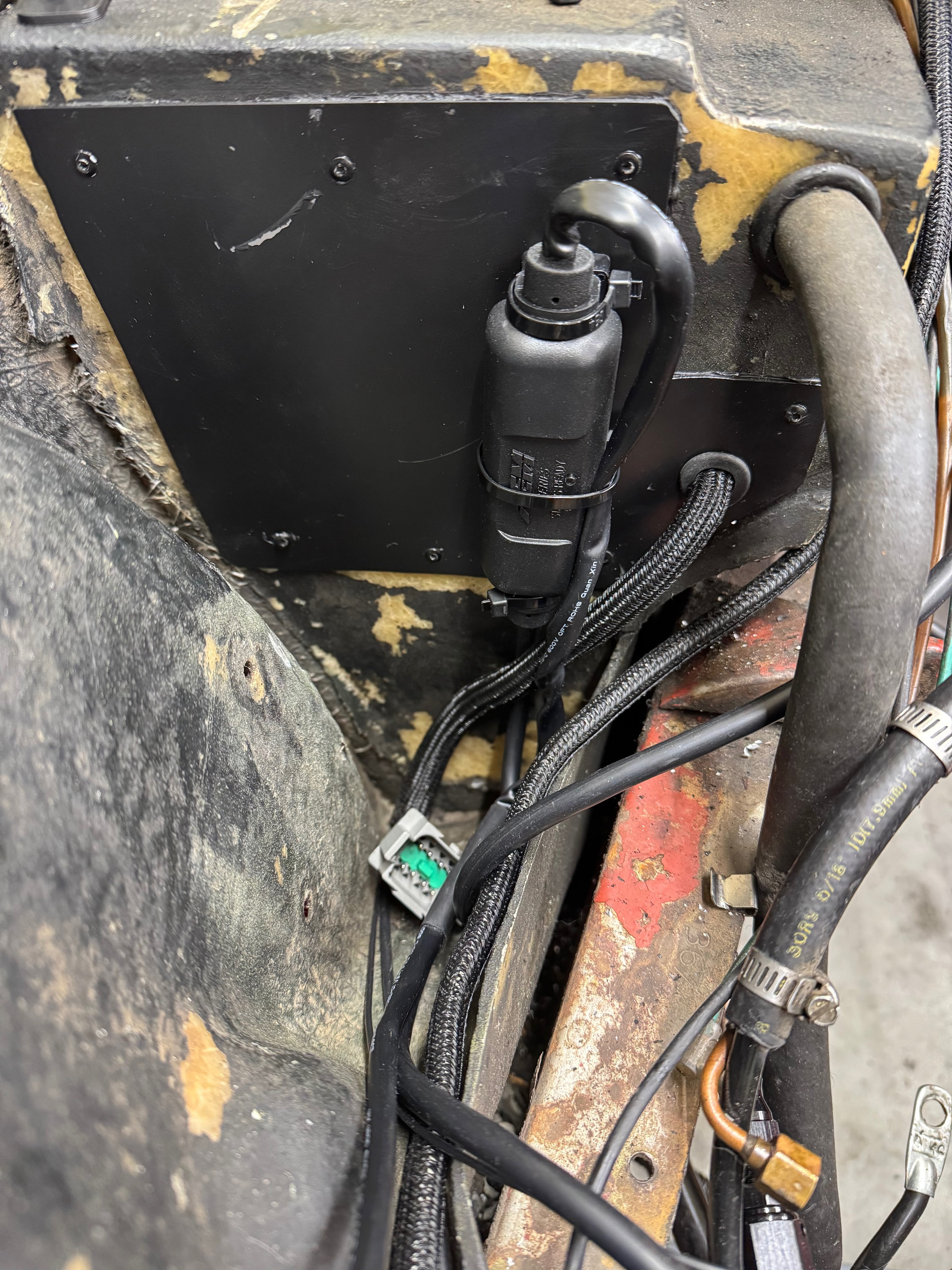
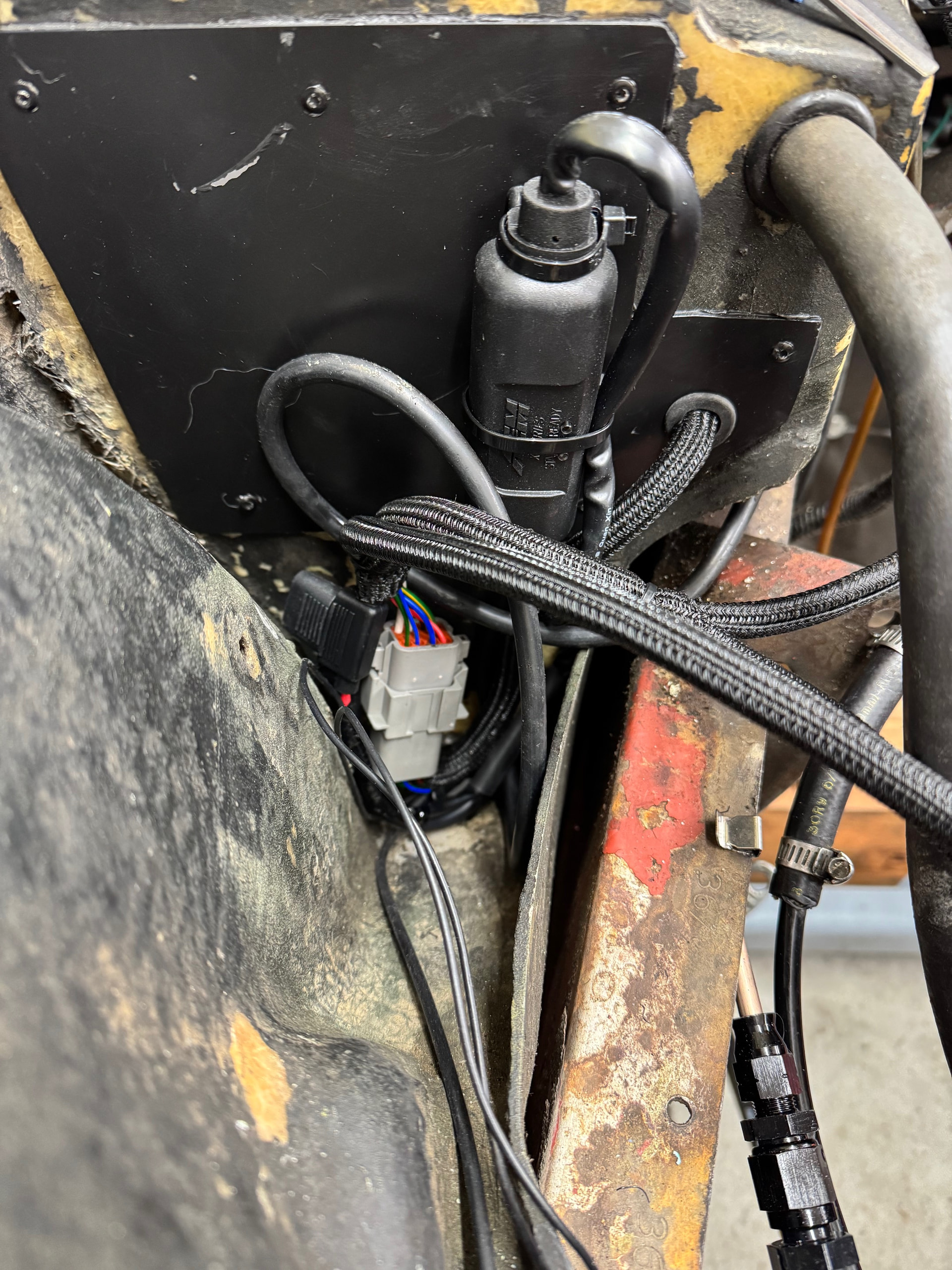
Once the AEM is here, I can start the Nodiz installation, but completing the loom will need to wait for the QED parts to arrive, followed by another engine test fit to determine lead lengths. The NodDiz will mount via velcro to the cubby under the passenger side of the dash next to the side of the body, and the WBO2 controller will be on the other side of the firewall under the airbox
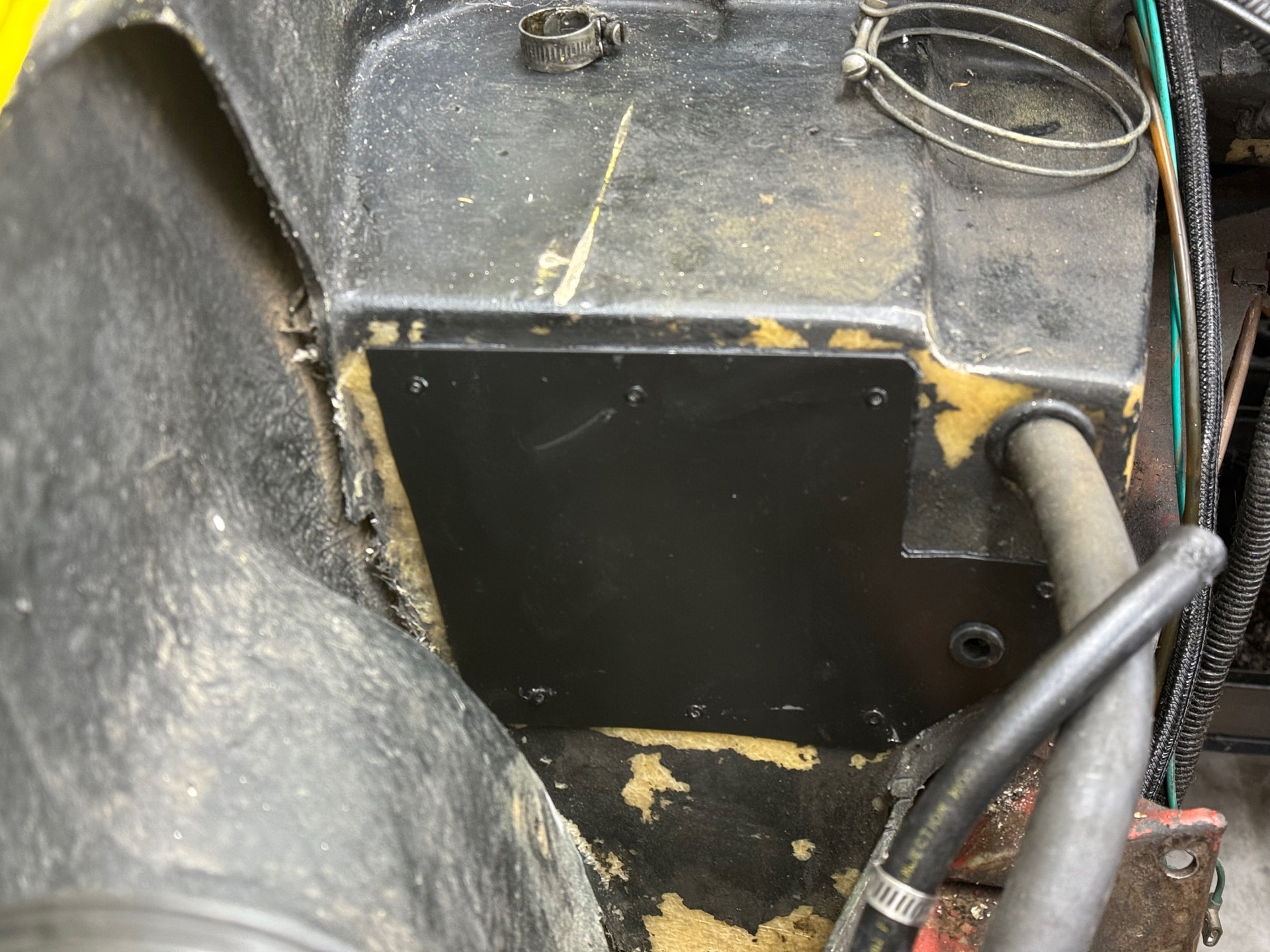
The pressboard cover for the unused RHD holes in the firewall was replaced with an aluminum piece that won’t warp or delaminate over time like the outgoing part. It includes a hole just below the heater hose for the ECU harness. I’ll either mount the WBO2 controller to this part or to the inner fender well immediately beside it.
I recently compared my air box to a factory item on a Sprint. The nozzle angle is definitely wrong for an Elan, but should work as-is for a +2. I’m reasonably confident that the offset reducer mentioned earlier will resolve the fitment issue with the radiator brackets. This is another item I’ll tackle during the next test fit.
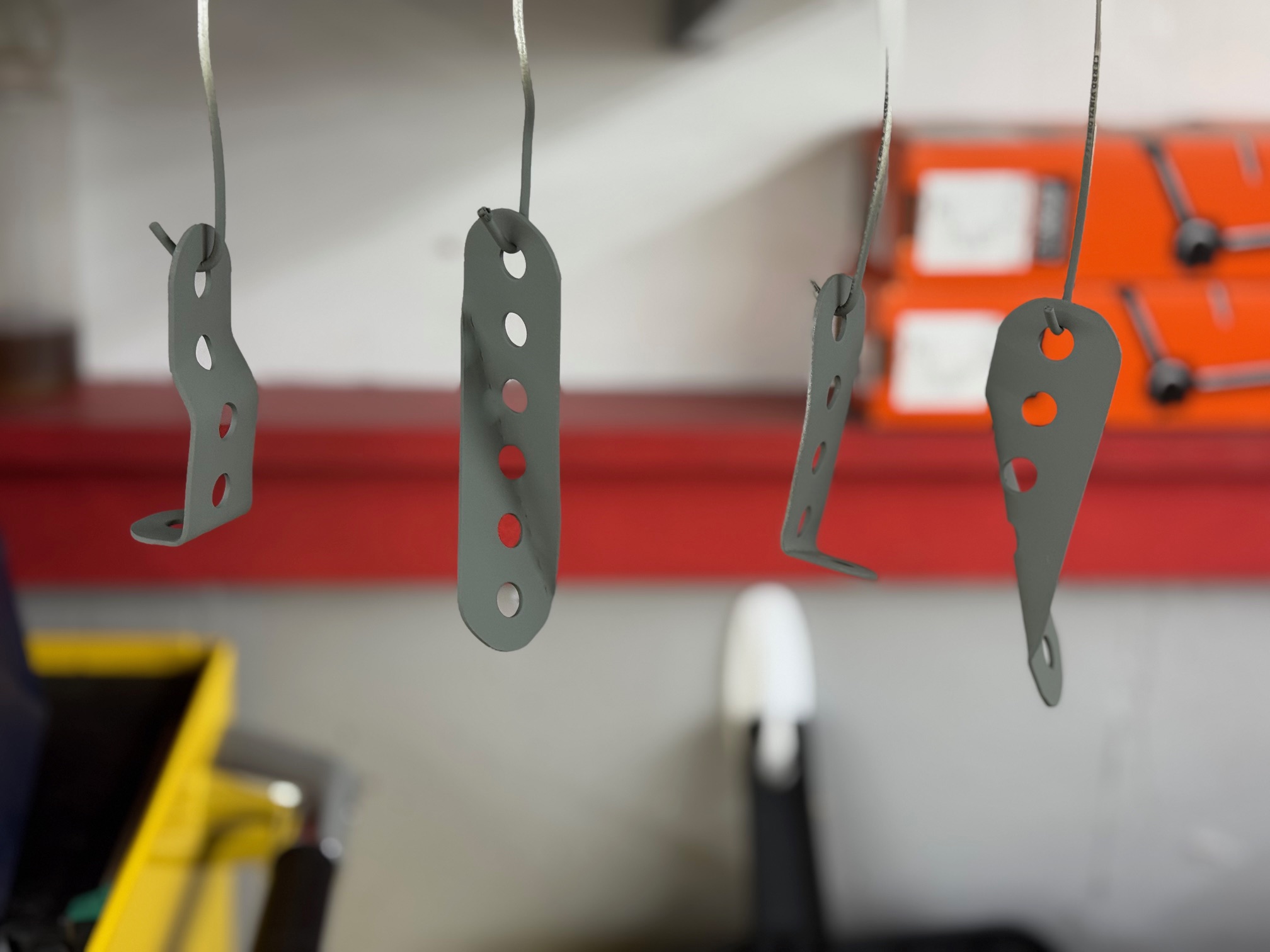
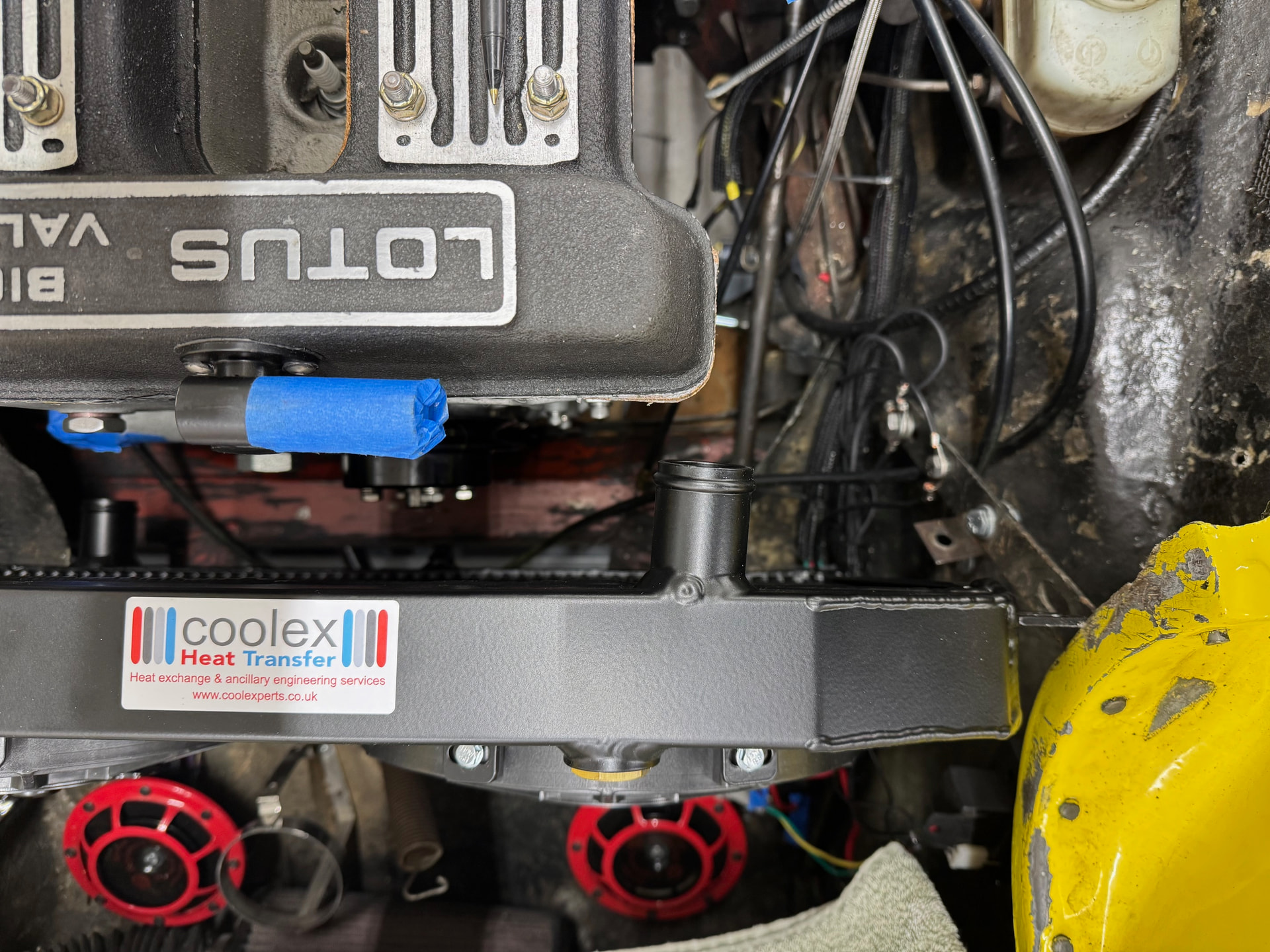
And speaking of the radiator brackets, new ones were required to work with the Coolex. I suspect part of this is due to some potential modifications made to the car’s existing brackets when it was converted to the wider S3 radiator, and part because of my desire to add rubber spacers to help with vibration mitigation. I’m not a fan of rigidly mounting an aluminum radiator. The primer coat is drying at the moment, but I’ll post installation photos after the finish coat is applied and fully cured.
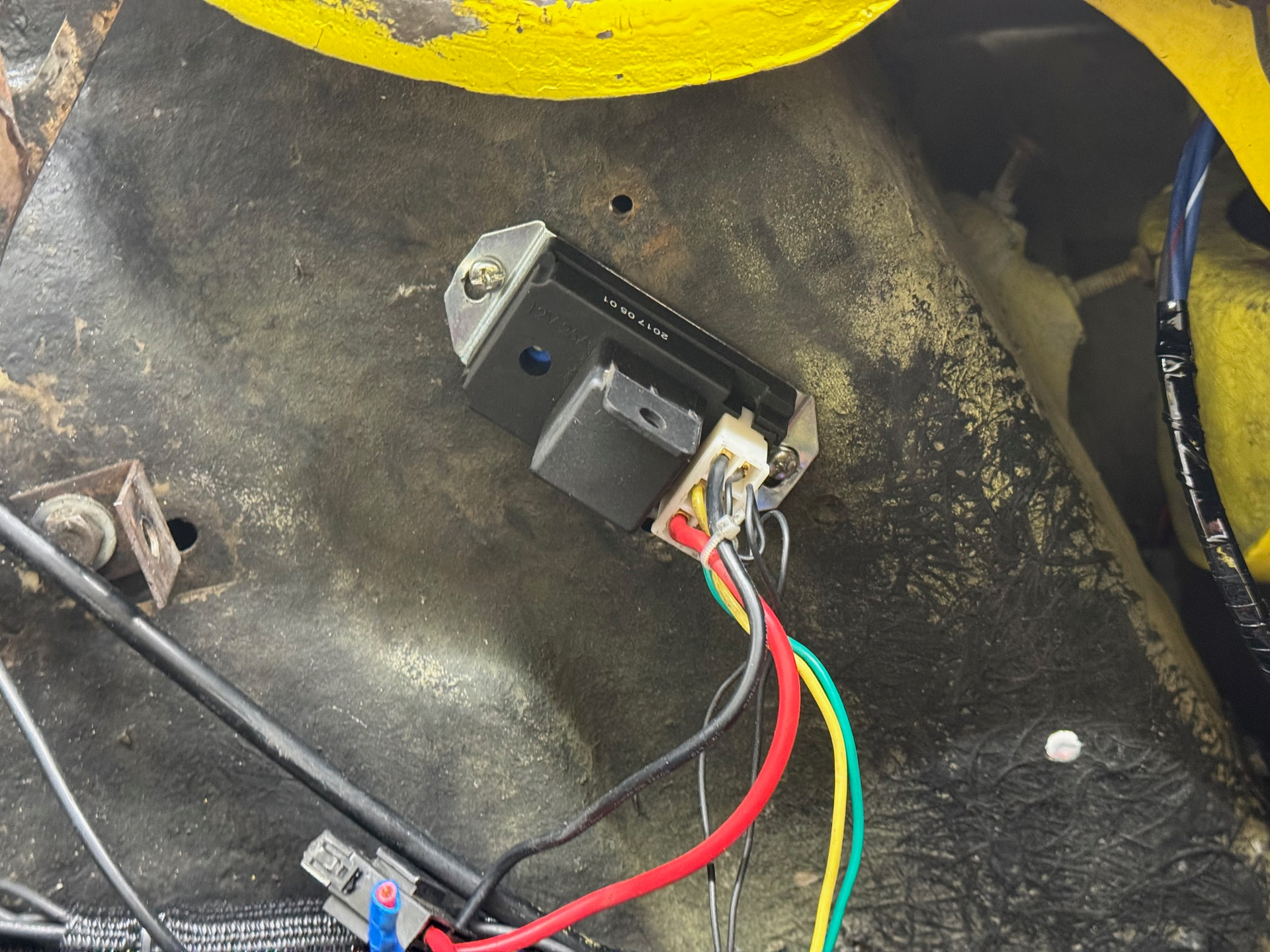
I’ve also moved the adjustable fan controller installed by the PO from the engine bay to the nose cone in front of the radiator where it’s hidden from view but still easy to access to reset the fan turn-on temperature. It’s something I should have done when rewiring the car last year.
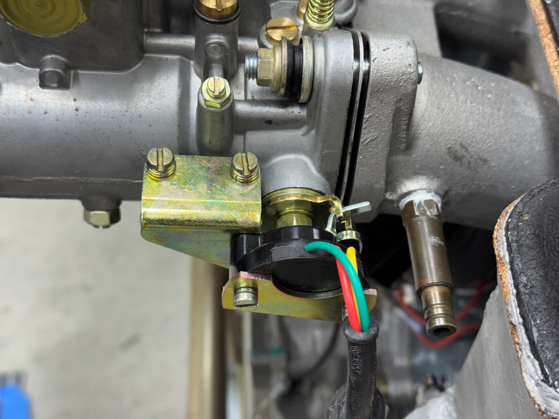
The throttle position sensor is now mounted. It’s a simple bracket that uses existing holes on the carb body and took all of a couple of minutes to install. Adjustment will wait until the engine and ECU are installed.
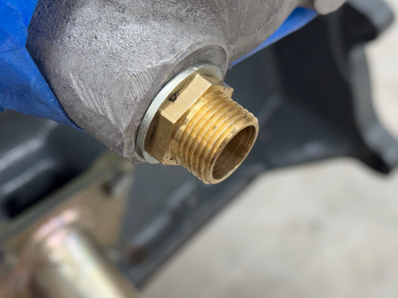
The new engine’s thermostat housing ports for heater control valve and coolant temperature sensor adapter have visible thread damage. Trying a borrowed, stock sensor adapter and some other adapters with different threads I had on hand, leads me to believe the temp sensor port was either re-tapped in the past, or a 3/8 BSPP fitting was simply screwed in with some force. The factory tapered adapter is too short to grab sufficient threads to seal, but the BSPP screws in enough that it should seal with a dowty washer and thread sealant (belts and braces approach). The 3/8" BSPP to 3/8" BSPP adapter I’m using is a spare that came with the Racetech mechanical temperature sensor I ran in the Westfield. To my surprise, the Smith’s bulb is a larger diameter than the Racetech’s and required the adapter’s through hole to be enlarged from 29/64" to 1/2".
As for the heater valve, it would only screw in 1-3/4 turns and was pointing in the wrong direction. Carefully retapping it with a 3/8 BPST results in the valve now turning 3-1/4 turns by hand before stopping, with another 1/4 turn required to point in the right direction. If one or both of these “fixes” don’t work, I may have to drill out the threads and repair them with a helicoil or equivalent.
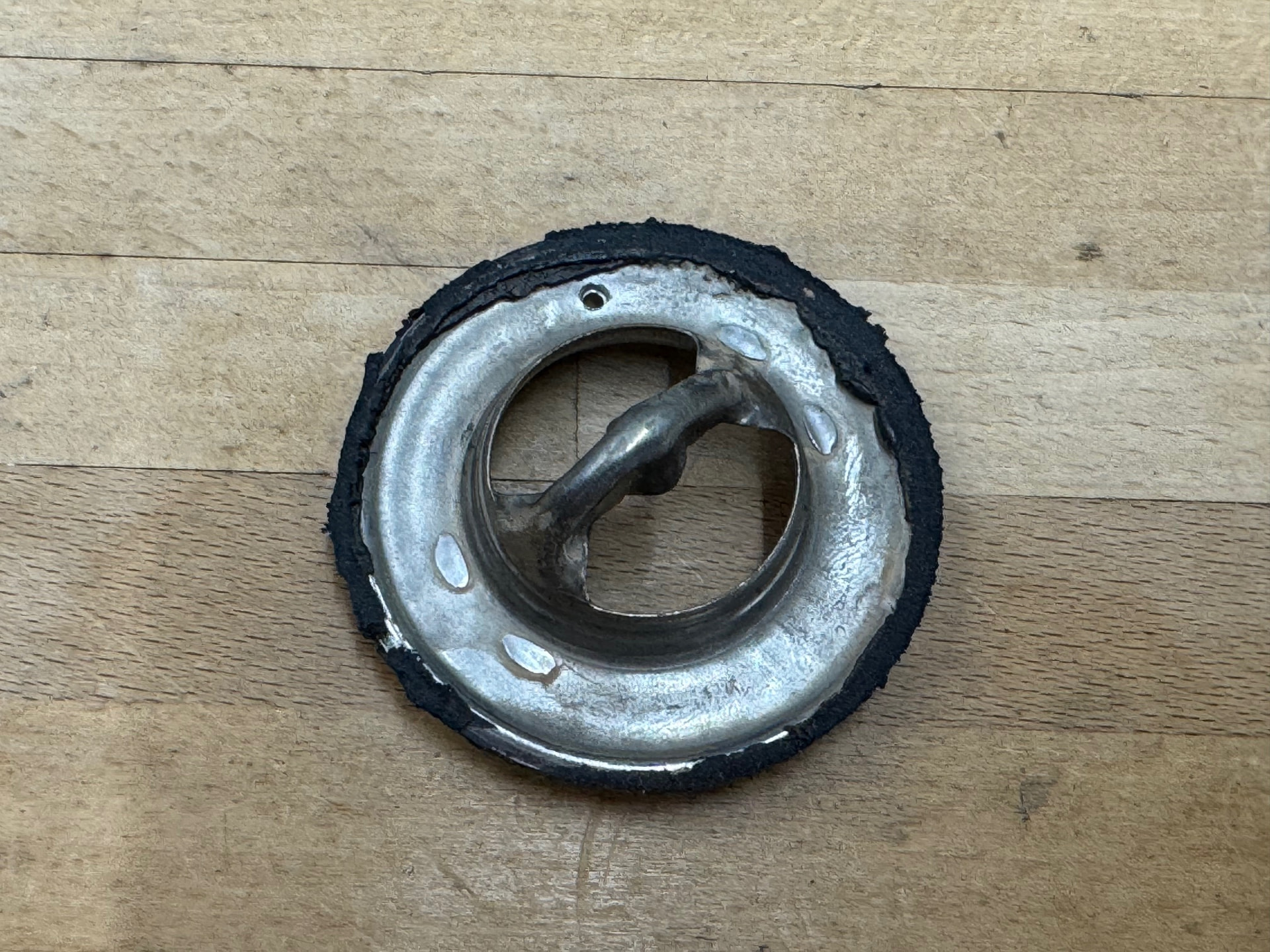
While attempting to figure out the issues with the ports, I removed the thermostat cover from my old engine only to discover it was hiding a gutted thermostat. I have no idea if this was done before, after, or as part of the upgrade to the S3 radiator. Regardless, a functioning replacement is planned.
1 Like
On Tuesday afternoon, FedEx requested photos of the QED package contents, which I sent off a few minutes later. That night, I received a message that I owe $54 in tariffs on the $155 shipment, plus a $15 processing fee. I hoped this meant they found the box that’s been missing since the 19th, but no. It didn’t. Because on Wednesday they sent a message stating they have been unable to locate the shipment and to contact QED for next steps. I asked them to confirm they will remove the outstanding bill for tariffs and processing from my account to avoid any future issues — I don’t want incoming shipments placed on hold over a balance due, or for them to send this to collections. However, instead of an acknowledgement, I received another reminder on Thursday that I owe them $69. Sigh. I’ll make another phone call tomorrow. I’ll also make calls about the backordered flywheel, and the backordered parts from Dave Bean.
With the new front transmission seal in hand, the gearbox reseal is effectively done. The one remaining item is to install the speedo drive, as I forgot to order a new paper gasket for that part. I’ll have RD include that with the thermostat order I’m placing tomorrow.
I suspect the QED replacement parts won’t arrive for another 1-1/2 to 2 weeks. Rather than put things on hold any longer, I’ll do another engine test fit this week to finish the wiring harness for the NoDiz and AEM, and also to finalize and print the new offset air hose adapter. The final coat of paint on the new radiator brackets will be fully cured by then, which will give me an opportunity to put the radiator in place with the engine fitted to make sure I didn’t screw up any of that work.
How frustrating!!.. this is one of the headaches I was trying to avoid by making my own harness… and yet my order to DTAfast is in process and now I will have this upcoming headache myself.
I also have another package that cleared customs earlier this week and am waiting for the next update. Hope it works out!
FedEx informed me last night that once QED has filed a claim, and it has been approved, then I can file a separate claim to remove the tariffs and processing charges from my account. Oh, and rather than including the requisite form for that claim, they provided their customer service number and told me to call and request it. According to my notes, that will bring my total number of proactive contacts with them via phone or email to a nice round 10. Why do I think that’s not the final tally? @2mAn , I hope things go more smoothly for you.
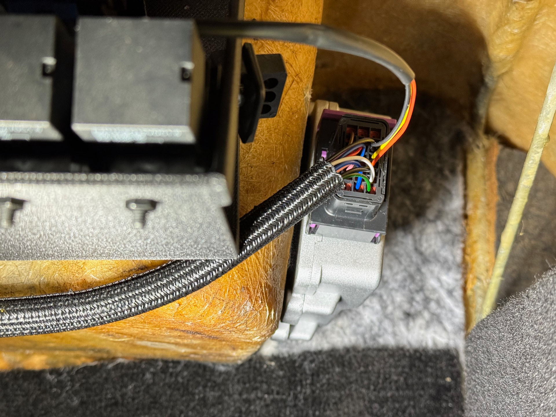
On other fronts, I tossed the engine in again earlier this week to finalize wire routing, check the new radiator mounts, and resize the air inlet hose adapter. The AEM WBO2 controller and Nodiz are both installed, and the wiring from the Nodiz is terminated in a Deutsch Connector. The wires to the other side of that plug and the AEM wiring will wait until the QED parts are here and I can finalize the wire lengths for my preferred integration path with the existing engine loom. Fortunately, that’s a quick job. I could take a stab at it now, but there is no point unless I’m trying to keep busy. It also gives me a little more time to stare at the engine on the stand and decide how I want to route and mount the wires for the coil pack, TPS, and CPS, as that could slightly change the length of the tach feed and 12v+ supply wires.
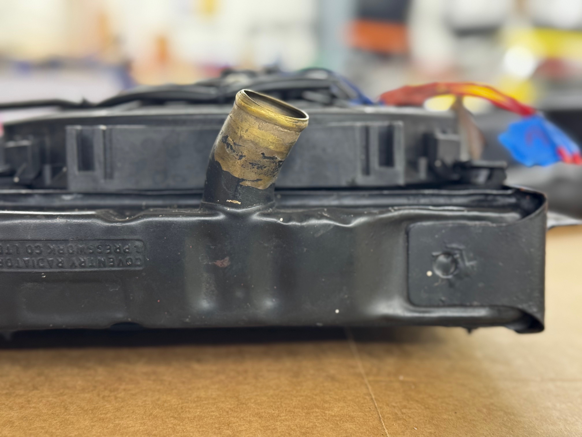
I had a bit of a scare with the radiator. Previously, I failed to notice that the upper radiator outlet of the Coolex is clocked at a significantly shallower angle than on the stock radiator as shown in the photos below. This results in the upper radiator hose touching the front corner of the valve cover. After tweaking a few things, I think 've freed up enough clearance for it to work, but it’s something I’ll need to watch. If there is rubbing, then I’ll need to get a little creative fabricating a replacement section of hose.
After changing the design of the air hose inlet adapter to achieve a good fit, I’ve decided to use that as plan B. With everything in place, it appears I can just route a flexible 4" hose between the end of the airbox and the radiator bracket — it’s close. If I can make that work, then I’ll simply make a 4" to 3’5" reducer to connect the other end of the hose to the air filter. It’s much simpler, but not as much fun (i.e. challenging) to design.
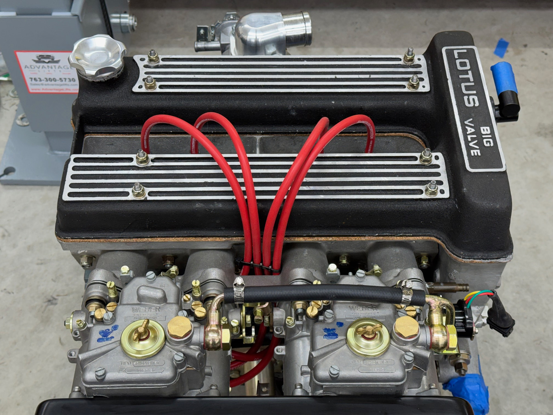
The custom length Magnecor wires arrived and fit well. That was a pleasant surprise given my general inability to measure something correctly the first time.
I’ve needed to ping Motorsport Electronics a couple of times; once to get a sanity check before bench testing the Nodiz, and another to confirm an inconsistency in their instruction manual. Both times, they responded in about 30 seconds via their chat interface. I’ve heard good things about their support from others, and so far, I agree with those assessments. Their ECUs are also quite well priced for the included feature set. If you’re in the market for one, I suggest including them in your research.
2 Likes
Good thread - build is looking very nice!
Thanks @ill_will , it’s getting there.
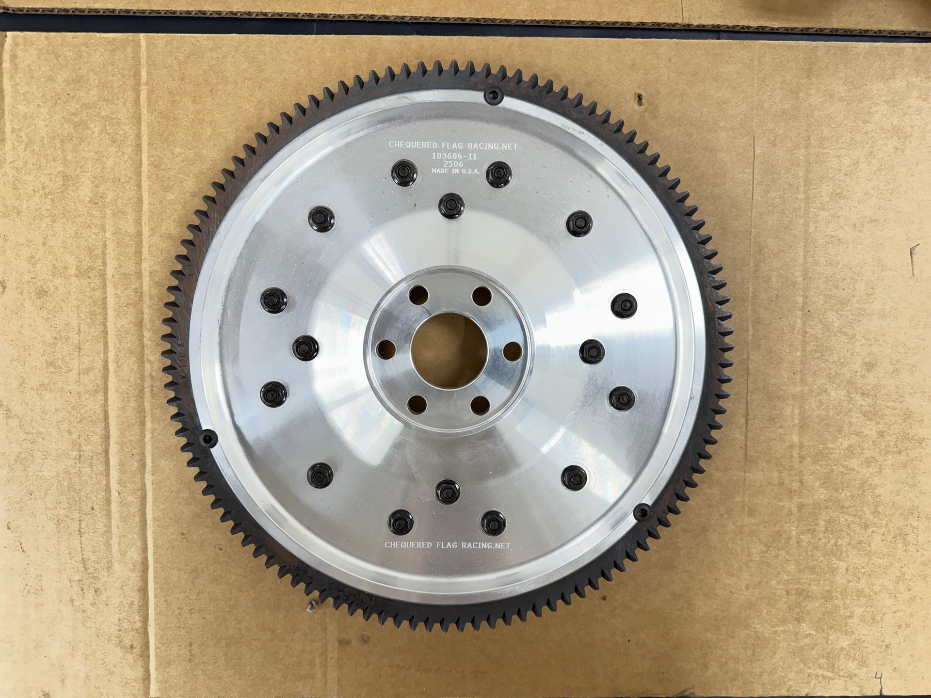
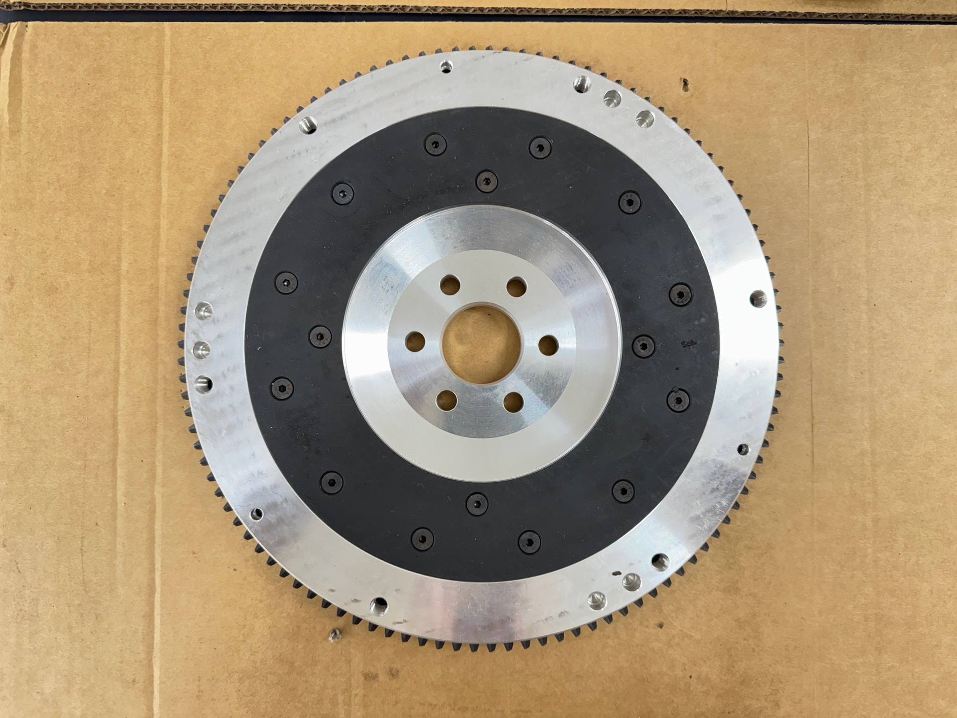
I forgot to provide a flywheel update. On Monday, Fidenza informed Jeg’s they still don’t have an ETA on production. While later speaking with Ken at Dave Bean, he mentioned a Tilton-designed flywheel made and sold by Checkered Flag in CA that he is running in one of his cars. Like the Fidenza, it’s aluminum with a replaceable steel wear plate. I didn’t hesitate. It arrived today. Just three days after placing the order. According to my postal scale, it’s a touch over 7.5 lb (3.4 kg) vs. a claimed 8 lb for the Fidenza. Coincidentally, the backordered clutch also arrived today. Progress.
BTW the flywheel includes a steel plate for the flywheel bolt heads that wasn’t in place when I took the photo.
3 Likes
Still no word from QED on when the parts lost by FedEx will reship. In the meantime, I’ve done a few remaining things that don’t need those parts to complete.
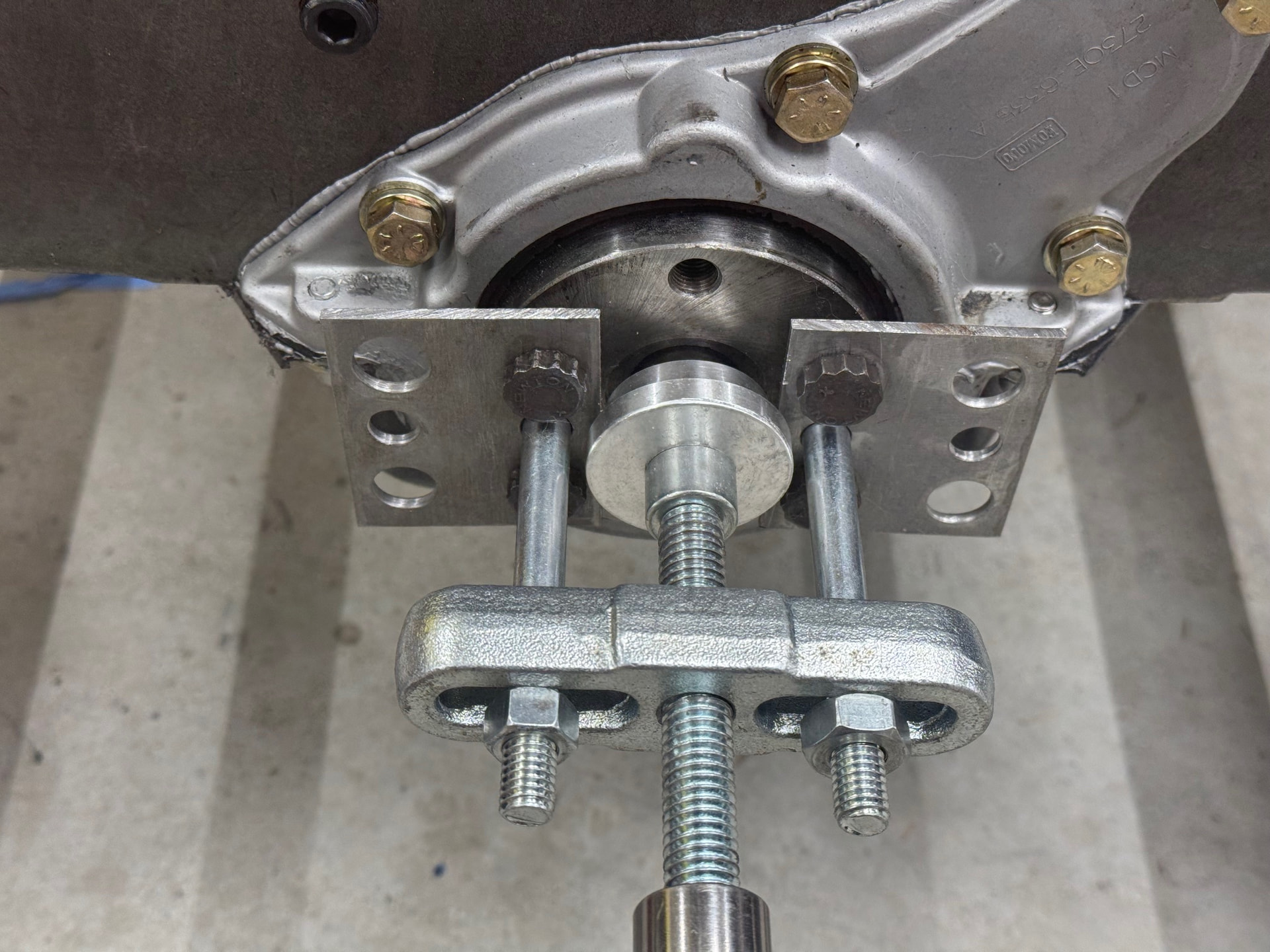
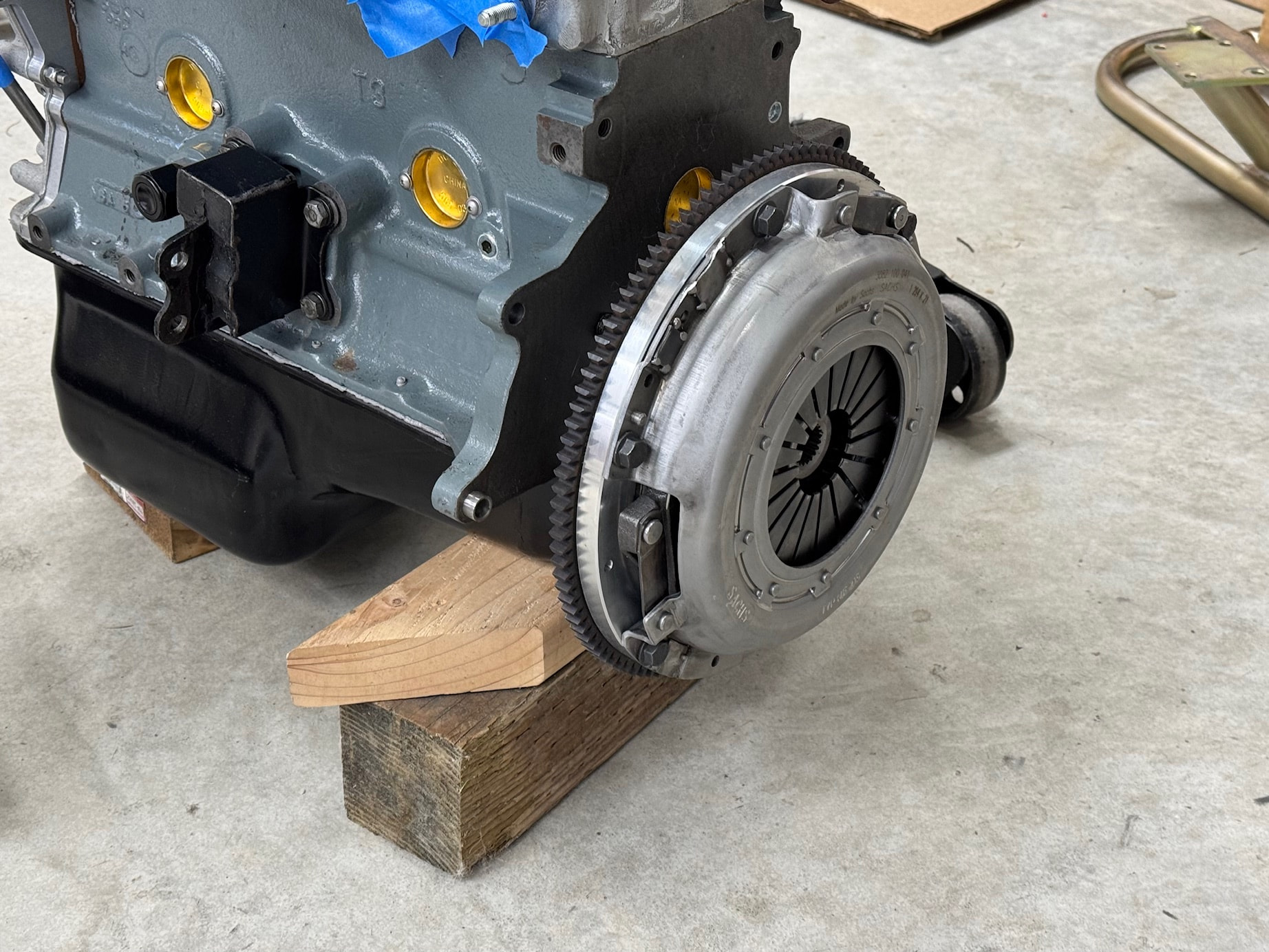
First, was having the flywheel and pressure plate balanced. The flywheel was off by just 1.1 grams and corrected to 0.5 grams, while the pressure plate was off by 7.5 grams and was reduced to just 0.3 grams. Those parts are now installed, along with the pilot bearing.
The Nodiz and AEM are wired except for the CPS sensor, which will be done after the QED parts arrive and the engine is fitted. This week, I’ll reattach the battery and make sure the Nodiz is picking up all the sensors and I didn’t make any mistakes wiring the Deutsch Connector.
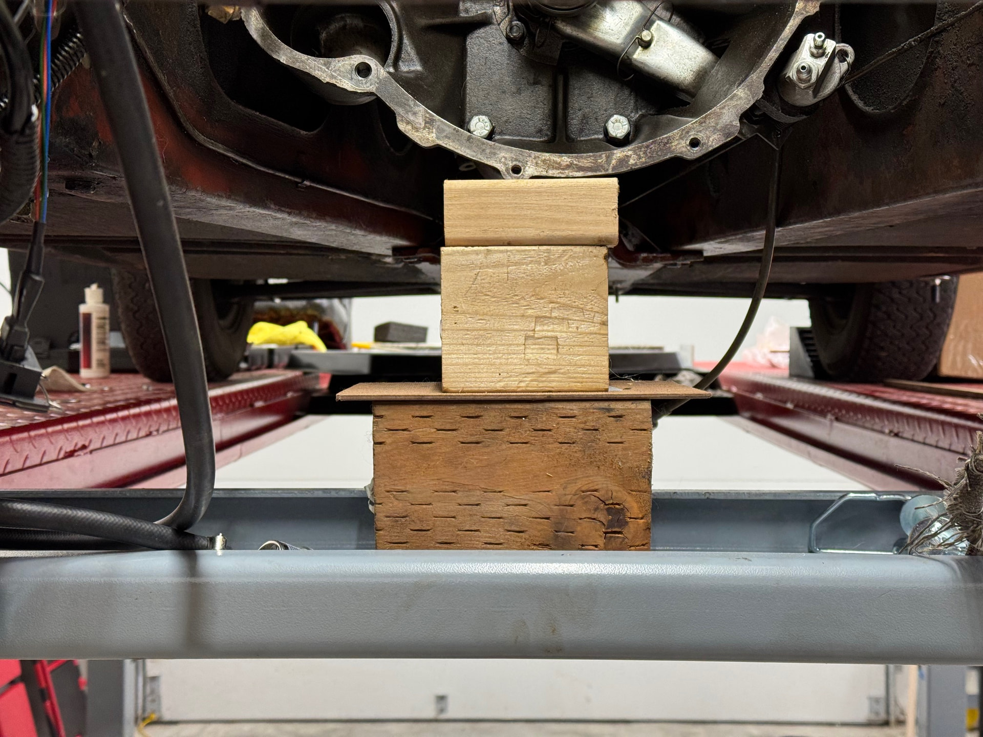
The transmission is also installed, with the bellhousing supported by wood blocks on the lift’s rolling jack tray. One issue during that process arose when removing the carpet on the transmission tunnel to access the port for the yoke. It turns out the adhesive I used did its job too well; small sections of carpet stayed in place, pulling tufts through the backing and leaving some random bald spots. It’s fixable, but annoying given I just finished that job over the summer, and it came out really well. Hopefully nothing will be visible with the tunnel cover and passenger seat in place.

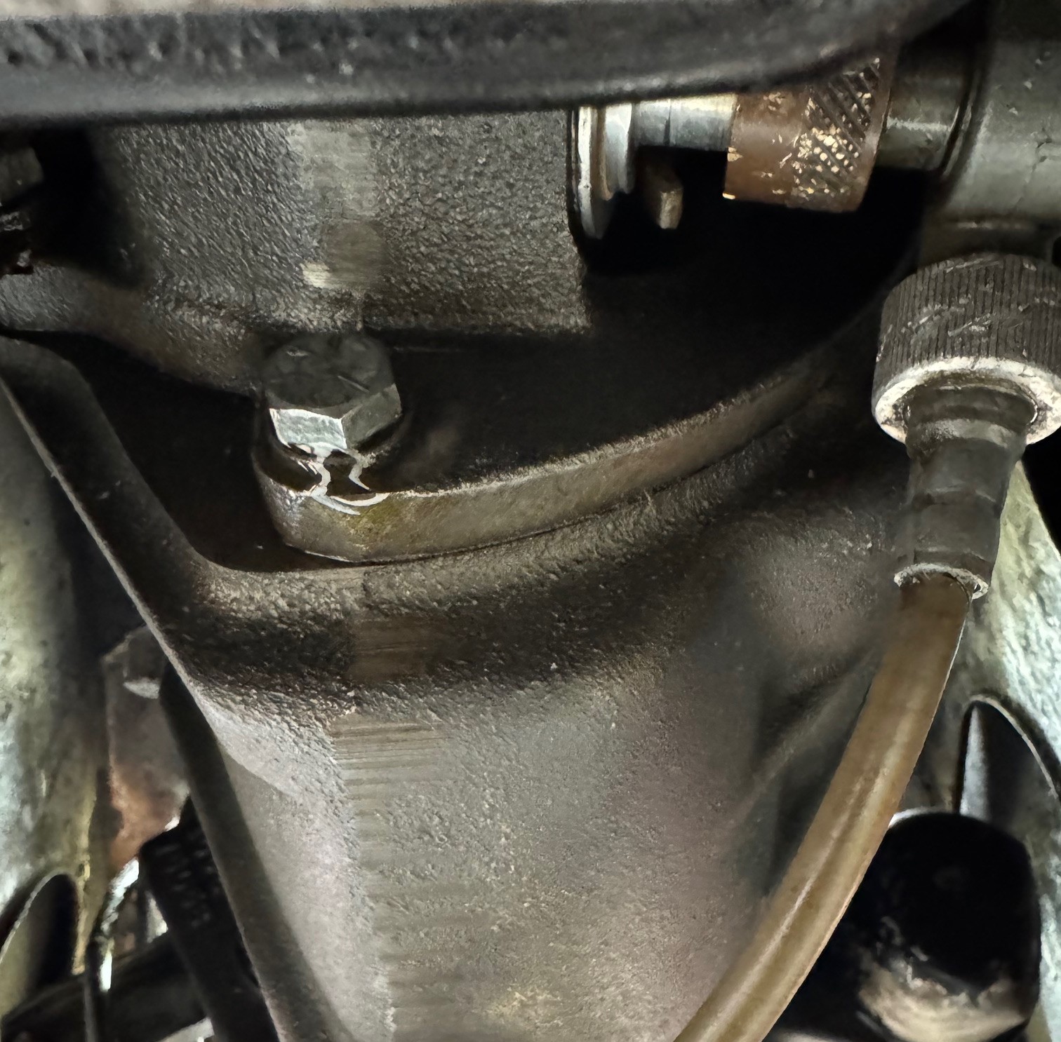
After several days filled with oil, there is very slight weeping from the bottom rear bolt for the tail housing that normally holds the exhaust bracket. I opted not to split the tail housing from the main case earlier since the other gaskets I removed all looked good and I didn’t want to mess with the shift rods. Does that bolt go into a blind hole or is it a through hole and the bolt must hold back the oil? I still need to attach the bracket and therefore remove the bolt, so sealing it isn’t an issue if required, but I want to be prepared if removing it will result in an unexpected oil drain.
Given the warped head discovery, I decided to verify the water temp gauge accuracy by dropping the bulb into 200F water (verified with an accurate thermometer) and checking again at 190F and 180F. The dash gauge consistently read 10-12F high. The fact that it’s off doesn’t surprise me, but I expected it to underread, not overread. Does anyone know if this discrepancy is normal?
When trying to test fit the 2" silencer, I discovered the Sprint style mounts differently than my SE’s twin pea shooter style. In addition to the rear mount, the front attaches to the underside of the boot with two rubber bobbins. Those are on order and that will probably be the last bit of work I can accomplish until the missing QED parts arrive.
Yes, that bolt goes through a hole totally open in the case. Along with it ‘partner’ at roughly
9pm location (when viewed from the rear). You need to drain the gearbox, pull the bolts,
dry out the hole and use thread sealant on the bolt threads.
1 Like
@gjz30075 , thanks for confirming. I assumed this was the case based on the nature of the weeping (only around the bolt.) I’ll order more gear oil so I’m prepared and will seal the bolts correctly.
The mounting bobbins for the front of the TTR 2" muffler arrived Monday evening, so decided to test fit the new exhaust yesterday. First, was installing the new exhaust bracket that attaches to the gearbox. Unfortunately, this led to the discovery that the jig used to manufacture the bracket is off. The spacing of the two holes is off by 2-3mm, which prevents the two bolts from threading into the gearbox. A couple of minutes with a round file to elongate the lower bolt hole and the spacing issue was corrected.
Next was drilling the holes in the boot for the muffler bobbins. I dug through various threads to ensure I was doing this correctly and then carefully positioned the two new holes to center and level the muffler.
It was at this point I forgot the cardinal rule when using non-original parts. A rule that should have been reinforced by my experience with the gearbox exhaust bracket. Never trust new parts to fit correctly or as advertised.
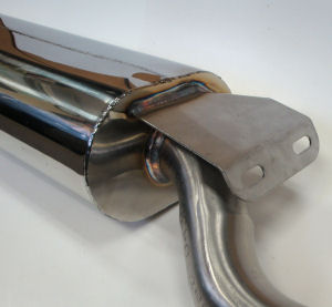
After mounting the front of the muffler, I stood back and saw that it was horribly askew. (sigh…) At this point, I detached the muffler from the bobbins to examine the bracket TTR welds to the front. Not even close to level or being centered. It appears someone had several pints at lunch before pulling out the welder when assembling my part. The top photo from RD’s site shows the correct bracket location. The second, shows mine.
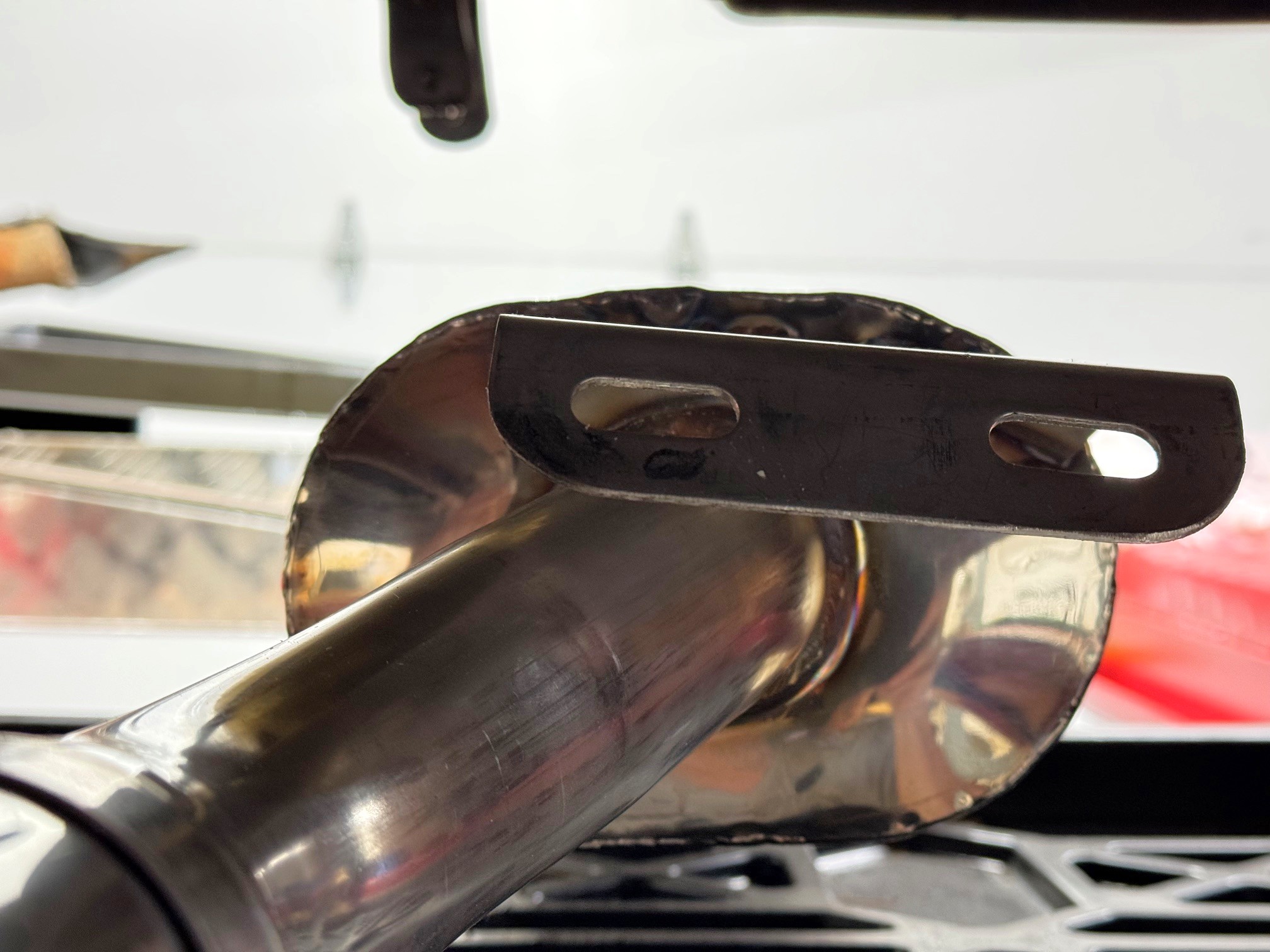
My first attempt at correcting this failed. Although a level on the muffler appeared to show the passenger-side bobbin needed to go up by 8mm, after making that correction and standing back, it seems the hole should have been raised by 12mm. (double sigh…) Rather than risk needlessly adding more lightness to my car through further measuring mistakes, I plan to wait to redrill the hole until the engine is installed and the exhaust is attached to the header. Hopefully, this will remove any positioning variables, and I’ll get it right the third time.
1 Like
When I called on Wednesday, QED said they would resend the missing parts shipment the following day. When I followed up 24 hours later to confirm they had gone out, I was told there was no tracking number yet but that the parts had been boxed and were waiting for pickup. Now that another two days have passed without a FedEx shipping notification, I’m not overly confident that actually happened. Fingers crossed that’s just my natural pessimism talking.
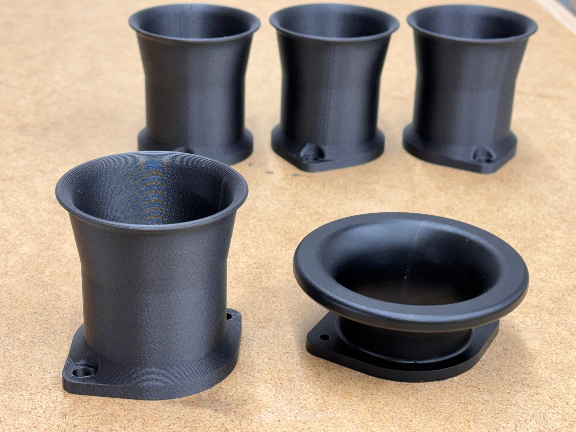
In other news, I had planned to print extensions for the air horns supplied by Omnitec. While they are beautifully made aluminum bellmouths, at only 35 mm long they tend to favor top‑end power over mid‑range torque. My goal was to significantly increase their effective length, but I quickly found that spacing out the #4 air horn by any meaningful amount introduced fitment issues. Even without a spacer, the edge of the bellmouth already meets the airbox base, and because the airbox lid narrows as it moves upward, adding length would prevent it from closing.
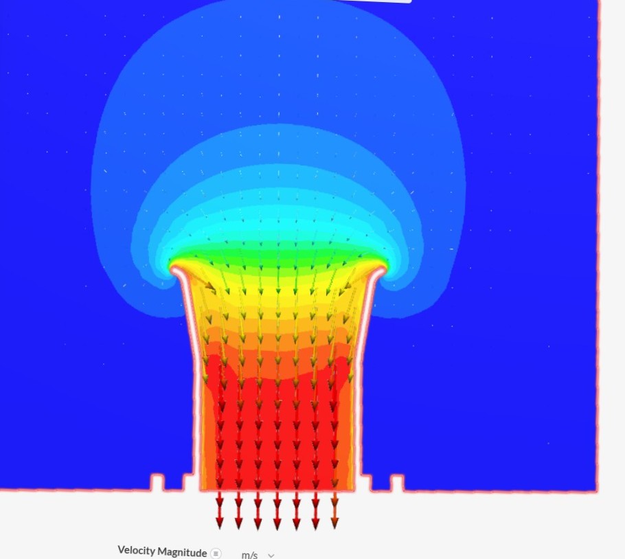
Plan B was to either buy 2-1/2" Weber air horns or design my own. The latter sounded more interesting, so using ChatGPT, I worked through an air‑horn shape that balanced overall length, outer lip diameter, and an appropriate flare to reduce the risk of airflow separation. Those results were modeled in CAD and a test part was printed. After a few small adjustments, I ran the design through a CFD package to check for glaring problems. Surprisingly, the results look good —at least when compared to CFD data for other air horns that are generally considered to be well designed. The following photos show an Omnitech air horn next to the redesigned version, the CFD results, and the new airhorns attached to the engine.
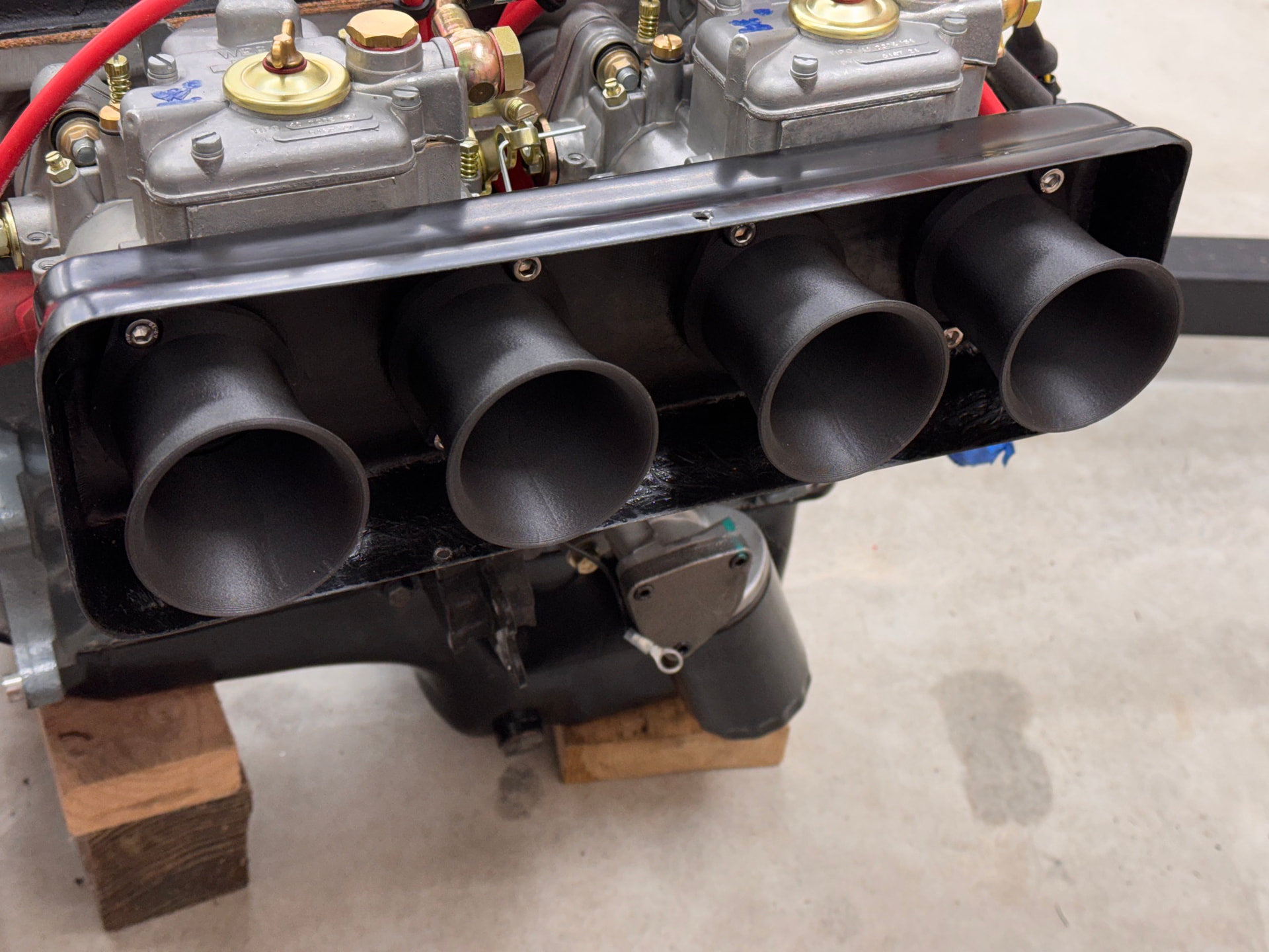
For the 3D printing nerds, I used PET-CF, which can easily handle under bonnet heat and is compatible with fuel.
4 Likes
Cool, I have a set of Jenvey heritage bodies to go on my engine and was wondering about trumpets and the viability of printing some. Yours look great.
A lot of people print them. The keys are using the right filament and minimizing stress risers that can lead to cracking over time from engine vibration. Filets and chamfers on the 90-degree transition from the flange to the main body help. These are the extensions I printed for the carbon fiber air horns I used on the Jenveys fitted to my Caterham nearly 3 years ago and are similar to my original plans for the Omnitech air horns.

1 Like
Awesome update John! Cant wait to see the final result in the engine bay.
Thanks, me too! If I had known that going with a 3D ignition would delay the project by 3 months due to parts issues, I would have stuck with my 123 Ignition and done the 3D system as a future upgrade. There is still no shipping notification from FedEx. I tried calling QED this morning to confirm they package did go out but then remembered today is a bank holiday in the UK. I’ll try again tomorrow.