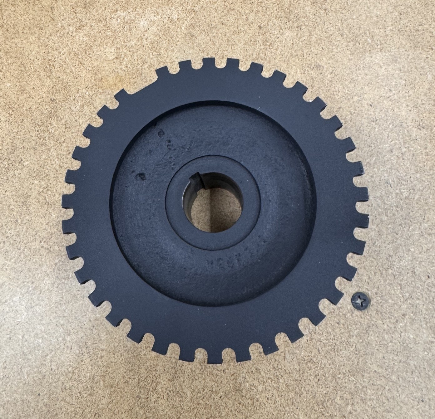
After the trigger wheel arrived, I had a local shop affix it to the crank pulley and true the edge on a lathe.
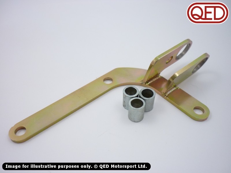
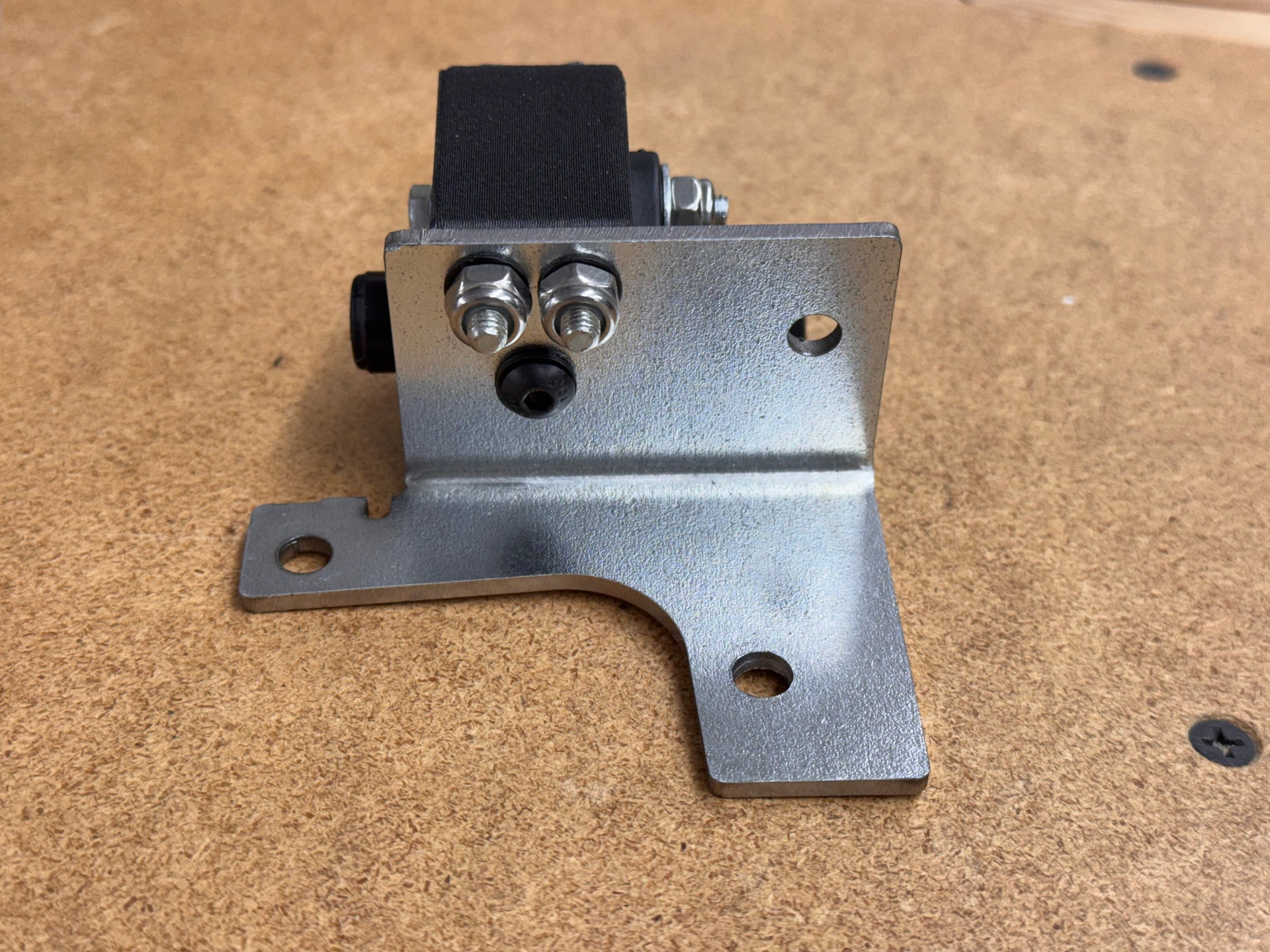
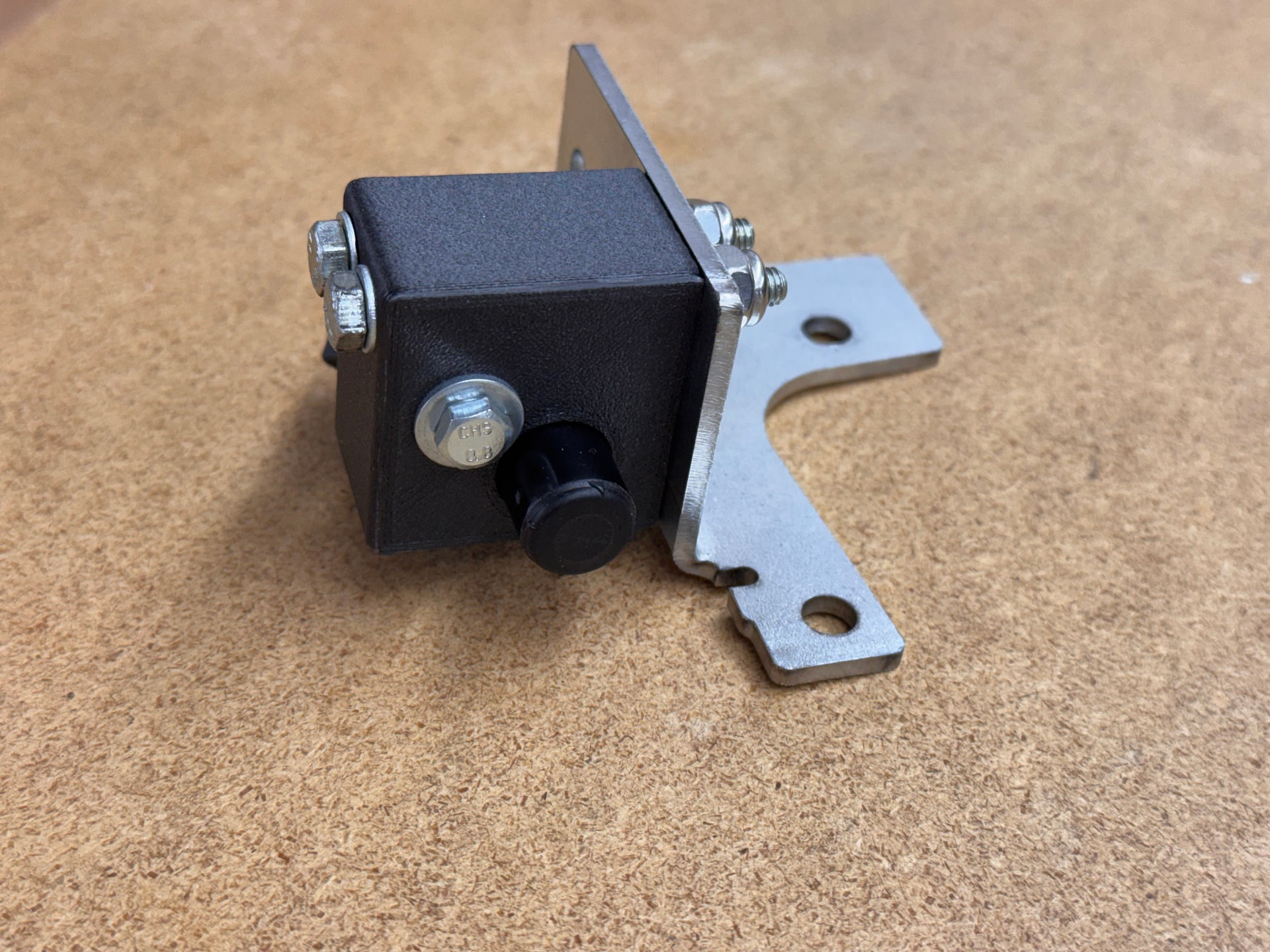
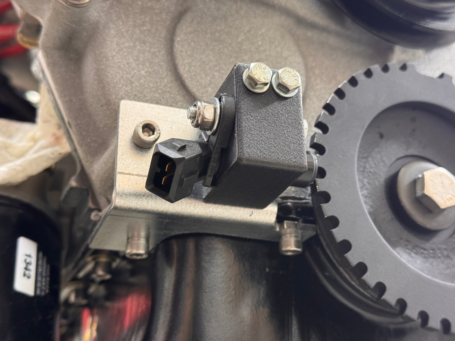
With that back in my garage and installed, the CPS bracket measurements could be finalized. Rather than follow the QED approach shown in the first photo below, which bolts to two of the oil sump bolts then holds the sensor with two metal loops and a bolt, I opted for a metal bracket that also uses a front facing timing cover bolt to improve rigidity. A 3D printed block bolts to the bracket and clamps the sensor in place. Doing it this way meant I could alter the CAD file for the block until test prints resulted in exact clearance between the edge of the trigger wheel and end of the sensor. Unnecessary overkill, but that’s part of the fun of this project. It also gave me an opportunity to try out the sheet metal features of the CAD package I use and try one of the online sheet metal cutting and bending services.
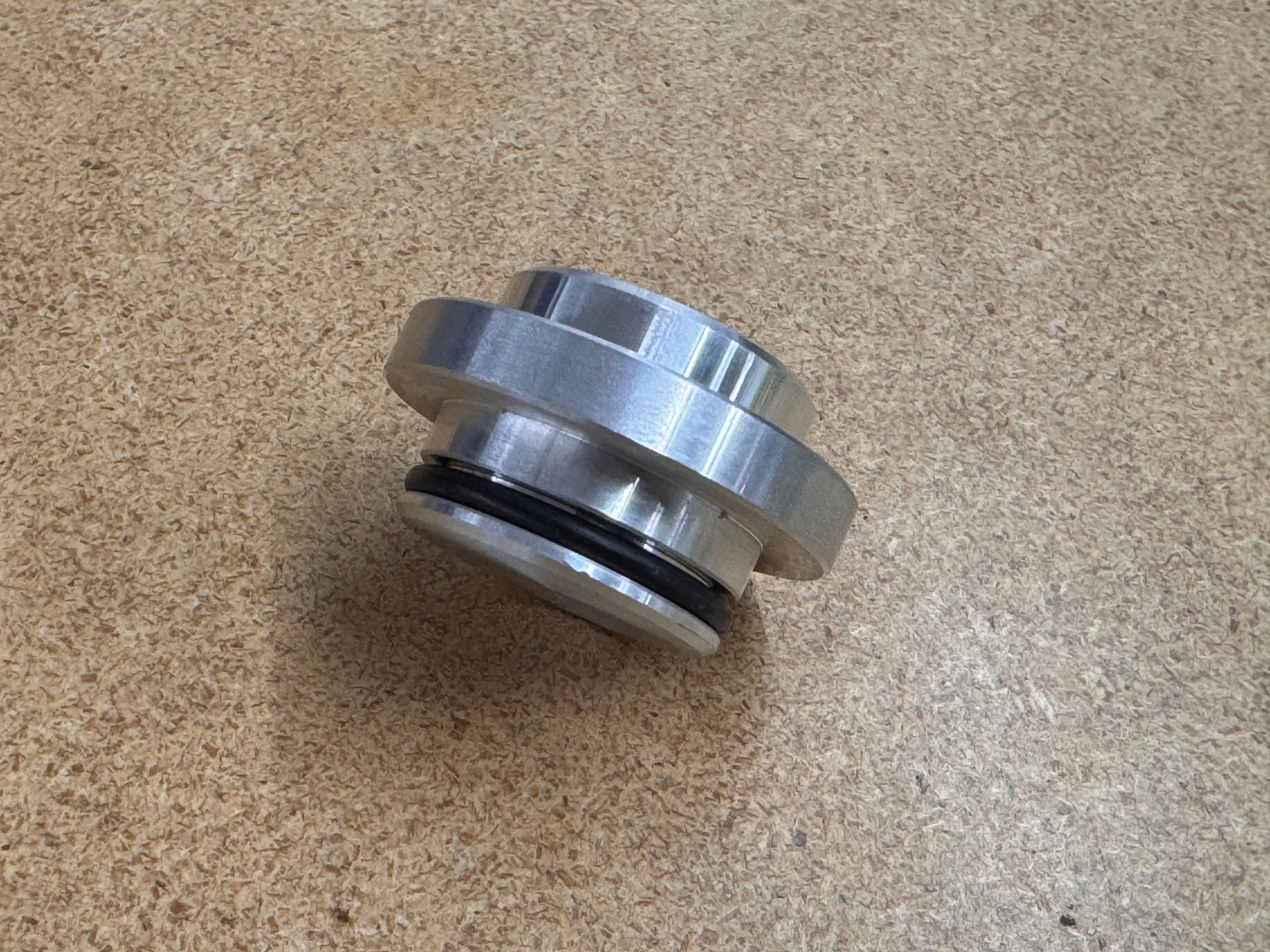
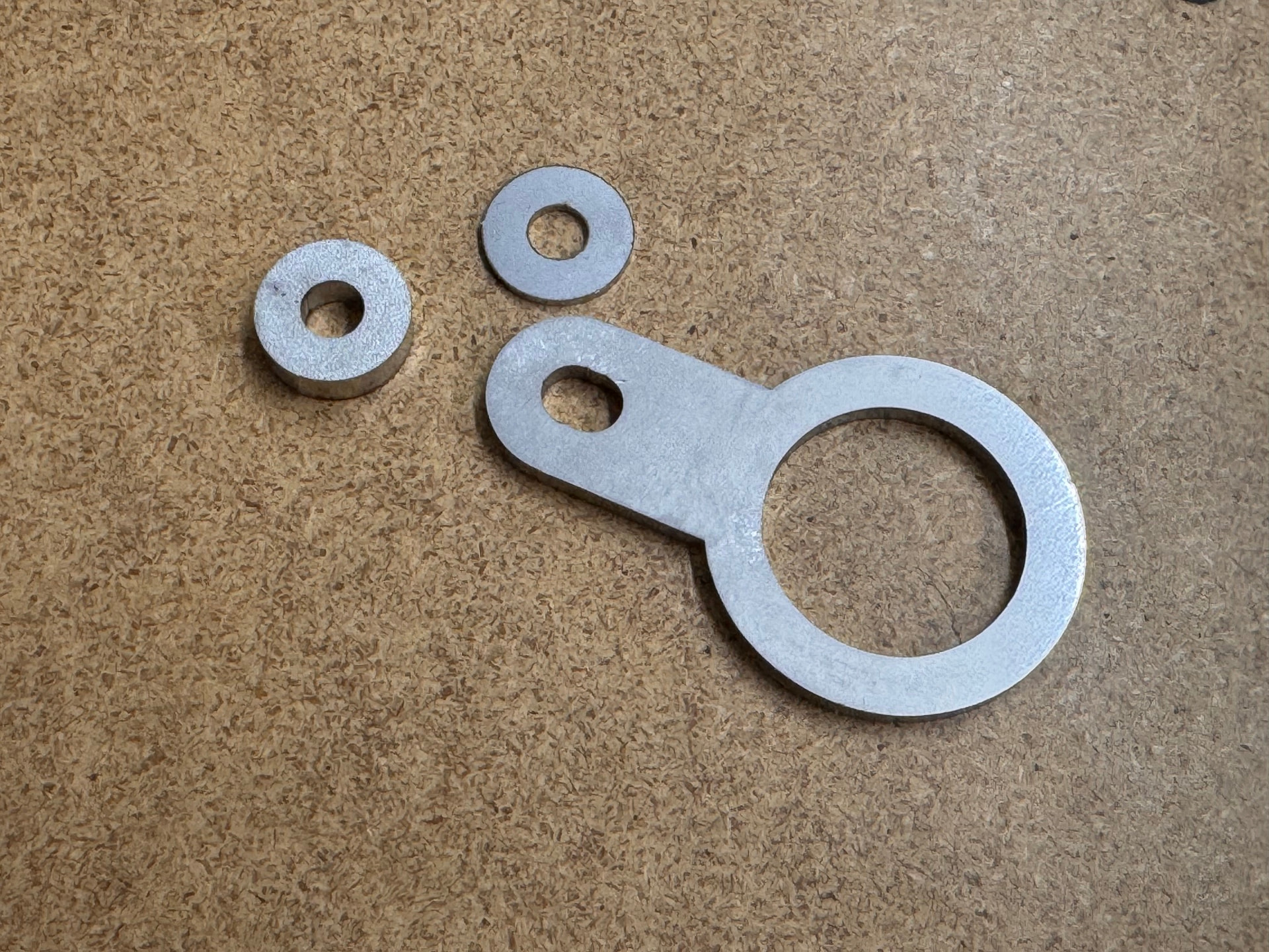
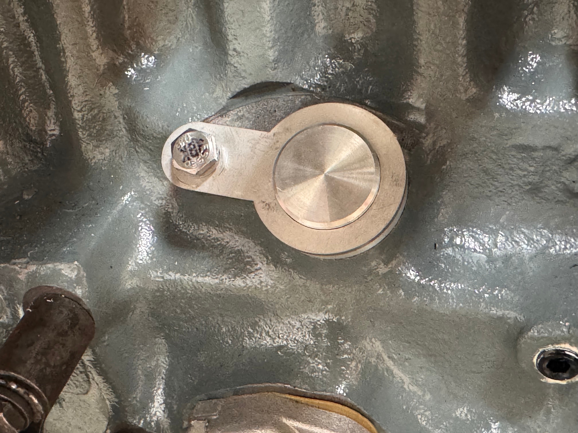
Next up was installing the plug for the now vacant distributor port. It’s well made and fits, but mounting it was a little problematic. The outer diameter was too large to use with the stock distributor clamp, and the top hat portion was far too small. Taking the easy route, I mocked up something the right size in CAD and had it laser cut.
The engine can now go in, however, a hand injury means that likely won’t occur until mid-July. Once installed, I can finish up the remaining jobs, the biggest of which is having the 2" exhaust mid-pipe swaged to fit the 1-3/4" RD header and have the bung welded on for the WBO2 sensor.