Hi All, I can see plenty of posts but can’t see the answer I am looking for, I need to replace the slave I think its over extended, I can’t see a leak from any pipe work so it must be from the cylinder and I can’t get any pressure in the line, its not the Master as the leak is coming from the bell housing. As it has been working the spacer must be about right or on the limit, I see multiple threads with reference to 17mm or 19mm. I can check this when taking the gearbox out. I can’t find a replacement slave, but see there are other option frmn the Mondeo that are said to fit although the hose may need rerouting. My question dose anyone have the actual spacer dimension, could anyone confirm what slave to use and lastly it looks to me like the face of the slave cylinder (bearing) is in full contact with the clutch, I am trying to think back many years but I thought the release bearing was not in contact with the clutch finger but maybe I am wrong and this is what the spacer dimension is so important, any advice would be good as I am planning to drop the gearbox out in a couple of weeks time and if I can get all the bits in hand then I should be able to out and back in all in a day (famous last words)
Andrew, I can help you in part. Im tied up at the moment but will try to revert by Saturday
Gavin
Andrew
I tied myself up in knots trying to sort mine so I resorted to a drawing which I enclose.
My slave has a reference CSC005. I have heard that Mondoes work but I dont know how successful they are.
The cast backplate didn’t allow the correct dimensions for me so I ended up making a spacer to get it to work which was done out of aluminium and was essentially an oversized disc, drilled to fit the mount on the gearbox and the slave unit.
My clutch housing is AP Racing (I think 2511-1 because I couldn’t find the reference on the housing. It is 215mm dia.) and the plate I am using is AP Racing (CP5351-1 23 spline).
My suggestion is to work out the dimension from the steel mounting plate where the box meets the engine on the engine side to get to dimension A on my sketch and work backwards from there to establish dimension B and then work out what spacer you need.
Don’t forget to allow for clutch wear.
The thing I don’t remember is whether I used the Ford spacer and the home made one or not - but when you work out Dim. B it will become very apparent.
I had a nut welded on the back of the clutch pedal and when it was installed, I tried various lengths of bolt to act as a clutch stop. As you have discovered, once it overthrows, it can’t be rebuilt. I felt the gear change at various stages and as soon as it changed from rough to smooth, I set the pedal there using a lock nut on the the clutch pedal limit bolt. This allows for future movement if necessary.
I hope this makes sense but if not, please feel free to revert.
Good luck
Gavin
Elan Concentric Clutch dimension drawing.pdf (365.8 KB)
One point - I’m sure I’m not using the full actuation range for the clutch to disengage - just enough for the fingers to release so although the drawing shows the full range, try to use just enough of it to get a clean change - self evident I realise but worth noting.
Gavin
Hi Gav,
So how do you limit this have you got a limit on the clutch peddle that would stop you over pressing, I can see from your calculation you would set the clutch fingers at the fully closed position so you have the maximum travel to depress the clutch finger, although noting that you probably only need half of this. I also had not apreceated that the cylinder would be in permanent contact with the clutch finger. Thanks for the diagram it makes sense of how to measure my set up.
Andrew
There are probably numerous subtle ways of limiting the pedal travel and therefore throw. 3 that I can think of are:
- Change the volume of the pedal slave cylinder (dont know enough about this !)
- Put a pedal stop on the floor
- Put a pedal stop on the pedal.
I went for 3 by having a long nut welded on the side of the pedal which allows me to adjust a long bolt that hits the upright part of the GRP bulkhead behind the clutch pedal. I played with the length of the bolt until I was happy that the gears changed nicely (but no more).
The last job for me is to have a washer welded to the bolt head where it hits the GRP to spread the shock a little.
I’ll try to send a photo
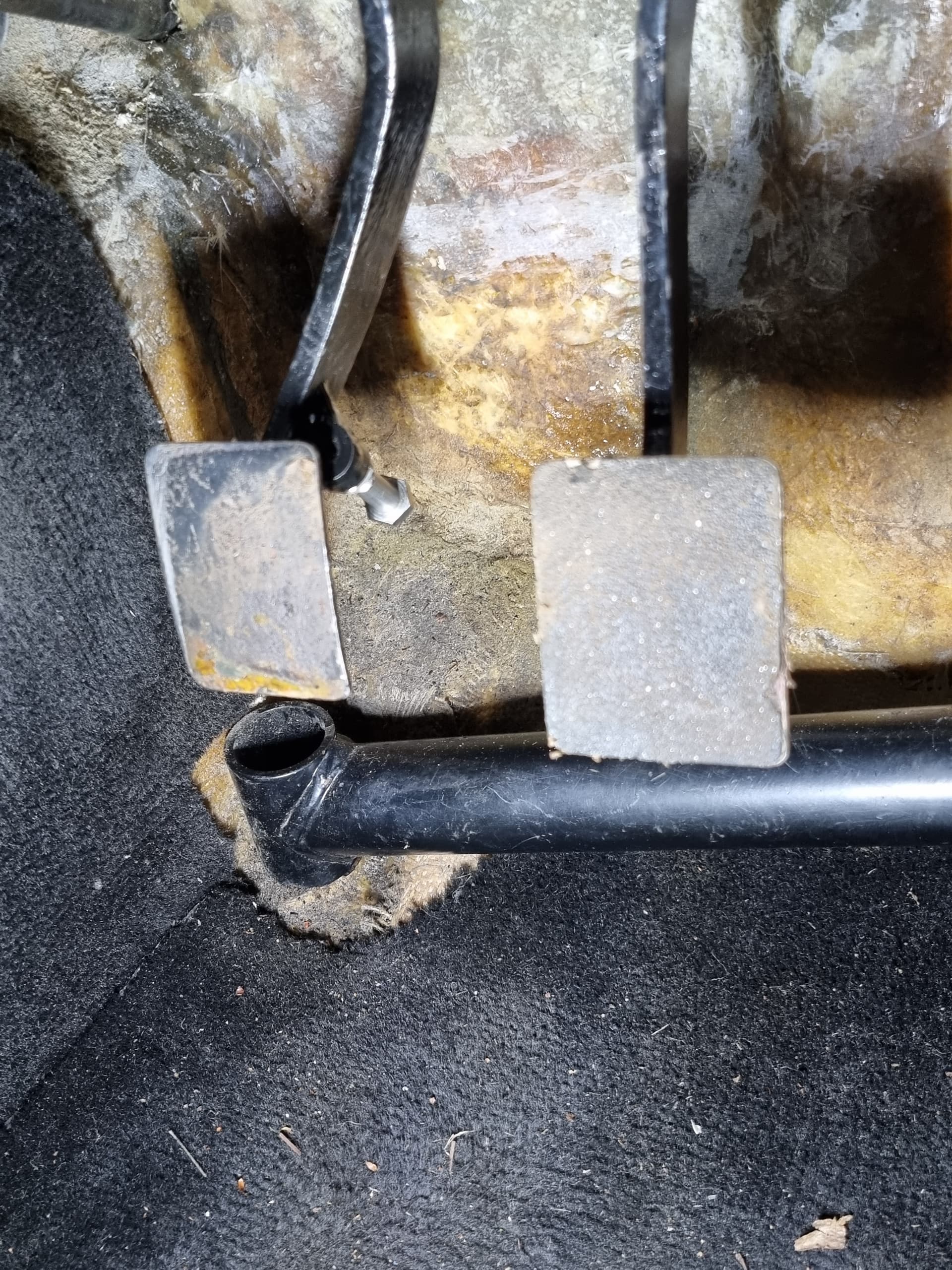
The footwell is standard but I have a TTR side bar intrusion kit and the pedals have been adjusted to fit my wide feet - other than that its standard in there.
The shoddy condition is because I am transferring from competition to road and I wont be starting the retrim until next winter.
However, hopefully you can see the nut welded onto the clutch pedal. When the pedal is depressed, the bolt meets the floor square on and I am going to make a spreader for the bolt head and a buffer on the bulkhead to absorb any shock.
It took a little setting up to get it right and is now spot on.
Hope this helps.