ME NODIZ Pro GEN-X install in a Plus 2

Quick follow up on the CPS connector.

It appears the correct connector for the standard Ford style crank position sensor is called up on eBay as:

eBay Item Number: 155351420391

RW 2 Pin Bosch Jetronic/Minitimer Quick Release Connector Plug CPS-035

Raceworks 2 Pin Bosch Jetronic/Minitimer Quick Release Connector Plug (Plug and Pins) CPS-035

Product Description:

Raceworks 2 Pin Bosch Jetronic/Minitimer Quick Release Connector Plug and Pins.

Raceworks have developed a comprehensive range of connector plug adapters and extensions, enabling a quick and simple upgrade to almost any application.

All Raceworks products come with a 2 year warranty.

Manufacturer: Premier Auto Trade

Taking a shot and ordered. Surprised an eBay search only found suppliers in Australia and the UK. Anyway, this should be the simplest way to get Stella on the road again.

Made some more progress on the NoDiz project.

Here is the wired ECU with two power supply relays. I installed separate relays for the ECU power supply and the coil pack power, which is already run within the NoDiz loom to the ECU connector block area, so a relay seemed to simplify things.

I used a direct +12v battery connection bus that was already available under the bonnet, right or passenger side. I already had added a 11 pin block connector in this area to accommodate previous electronic ignition installations.

The connector already has a very stout ground that runs back to the main ground bus on the right side dash mount, a couple of ignition wires that are now used to trigger the power relays and power the Wideband O2, a tach signal wire back to the refurbished Smiths tach, and some vestigial wires for the stock coil and dizzy. The stock security switch is long gone from my car.

As mentioned previously, I am using a fully terminated Zetec loom. The individual loom runs are too long for my installation, so unfortunately every run requires shortening. I would recommend trying to get a fly lead version of this loom and request they include any additional runs you want along with the appropriate connectors. Worth a shot but I don’t see this option directly offered on the Motorsports Electronics web site.

The loom is of very high quality, with individual runs inside plastic coverings. There is approximately 4” loose length of all the plug wires next to the ECU block connector (after easily unwrapping some non-adhesive loom tape) which provides easy access to the female pin receivers in the block connector (after un-clipping the back of the block connector and moisture barrier). The instructions indicated the new crimped pin receivers on the shortened conductors can be pushed through the flexible moisture barrier, but I found it easier to draw each raw wire through the gasket and then perform the crimps.

Using this method I shortened the three conductors to the coil pack, three new conductors to the TPS (should have specified this leg be added to the Zetec loom), and the unwrapped chassis loom wiring for power, ground, tach signal, Wideband O2 signal. Pin A6 (Black) is used for sensor grounds, which in my application included the Wideband O2 data pair (data wire routed to the dedicated A2 Inlet Air Temperature Sensor) and the TPS ground.

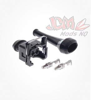
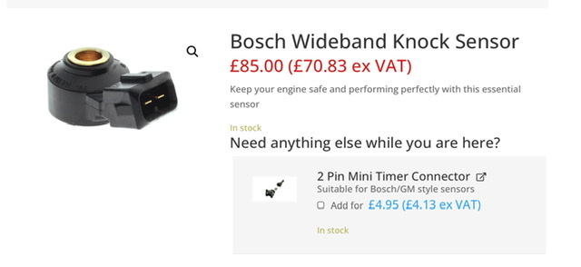
The exception is the CPS, which is two conductors within a grounded shield. The grounded shield shares pin B7 with the Serial RS232 ground, which makes shortening this run difficult at the ECU connector block. I used an easier approach and purchased a new CPS connector and shortened the other end. Note this is really easy because the ground shielding is just stripped back to expose the two conductors that are simply crimped to the standard pin receivers. The ground shield is not attached to the CPS connector. I don’t have the exact call up for the two pin receivers, but they should be very easy to source as a Mini Timer connector, saving the cost of a whole new connector. They are the same pin receivers as used on the Webcon TPS connector. The CPS connector has integrated moisture seals that can be reused with care.

I also made up a matching 11 pin connector that accommodates the original points and coil without too much fuss. Plan is to have the stock stuff in the boot.

I had to further modify the coil pack mount a bit. Once I fitted the spark plug leads I was fouling the carb intake runners. Note my engine is non-standard so may have somewhat different clearance in this area. At any rate, I removed the 1/2” spacer bar noted above, modified the packing washers, and re-drilled the coil pack mount, which lowered the mount away from the block. Unfortunately this caused some interference with the Plus 2 heater hose run, which is very difficult to access with the engine in place. The main point is it is pretty much essential to have the radiator out of the way, but I have not had to remove the carbs to get it sorted.

Next steps are to re-assemble the cooling system, check everything over, and try to start her up. I also still need to download the ECU software to our ancient laptop and connect the supplied USB to serial adapter. After initializing the TPS range, the biggest step is to set the timing of the CPS, which is individual for each installation. Apparently there is a zero advance setting in the ECU to make this one time procedure really straightforward. From then on the ignition map is all digital, and the base map is anticipated to be close enough to run the car.

I have got a promising lead on a local dyno shop for final tuning if required. A friend has his stock Weber Plus 2 in for a session now, so we will see how that goes, but at least we know the car will fit the rollers and they do a lot of carb setups.

So the main takeaway from this update is to have everything you can think of to hand before starting the installation. This included in my case the custom plug leads, CPS connector or pin receivers, wiring strategy into your car, correct TPS connector (mine was supplied with the Webcon TPS bracket and sensor), the firewall grommet, Wideband O2 connectors and the two sizes of pin receivers for the ECU block connector and some miscellaneous loom tape and plastic shielding. A top tip is to have extra pin receivers to hand as it is easy to miss-crimp one without practice to make sure of the required crimper.

I should add the ECU also has provision for driving an electric cooling fan relay and a fuel pump relay. If I were installing the NoDiz in conjunction with a full rewire I would probably use these features and centralize everything in the revised relay and fuse boxes. I already have an aftermarket fan controller and an electric fuel pump installed, so will leave as is. Keep in mind adding additional sensors could require additional conductors on the sensor ground pin A6, so plan accordingly.

Other features not required for our cars include launch control, cam position sensor, and knock control.

Hopefully we are up and running shortly.

Knock control is a useful feature if you can incorporate it. Around 10 years also one of the local Australian Electronics magazines published a DIY programmable ignition kit that incorporated it. It used a commonly available piezo knock sensor that could be attached to the block. Virtually all cars have a couple of knock sensors on the block these days.

Excellent suggestion on the knock sensor.

For reference, here is a link to the knock sensor Motorsports Electronics use. Looks like it would use a similar Mini Timer pin receiver as the other sensors outlined above. I would assume this would easily work with their programming software, which is at the “wish me luck” stage on my project. :smiley:

motorsport-electronics.co.uk/pr … ck-sensor/

I won’t be installing one at this point, but probably should have either specified the inclusion of a knock sensor leg in the loom or added the wiring while I was there. As already mentioned, this sensor (or the coolant temperature sensor required for the cooling fan relay option) would require attaching additional conductors to the sensor ground pin receiver in the ECU block connector.

I considered adding the wiring for these options, but man those pin receiver crimps are small! :slight_smile: Getting just two conductors on the crimp was reasonably tricky.

Just for reference, where is an obvious place on the TC to attach this sensor? Is it a bolt on affair? I am sure this is well trodden ground with the various FI installations.

Regarding Zetec loom options, I checked back on the Motorsports Electronics site, and this appears to be the listed best option for our cars. I may have confused what was available for loom options with some of their other offerings for their full fuel injection ECU, which has a fly lead option with an easy way to add the various connectors.

That said, I am thinking the online store offerings/details may have changed a bit from when I ordered. It could have been in a follow up online chat during the final purchase and shipping arrangements, but I recall having the option to specify which sensor legs would be included. e.g. I vaguely recall a drop down selection for inclusion of the TPS leg which I didn’t include as I was getting the Webcon TPS kit. It now appears both suppliers use the same connectors (perhaps even the same TPS sensor but not sure) so guessing it would have been easier with this leg added/included in the loom.

I am assuming they would be able to accommodate a clear request for an assembled multi-leg loom (using their existing generous length templates) complete with the sensor connectors but with none of the supplied connectors crimped in place. Might be way off base, but that would be worth asking about in an eMail. Unfortunately I wasn’t knowledgeable enough to ask for something like this when ordering.

The key point is Motorsports Electronics are quite responsive, but the whole purchase process is a bit distant from a complete plug and play kit that could perhaps be specified with a series of simple online drop down boxes.

Hoping my rather wordy writeup here will make it easier for the next guy. I am completely new to a project with these complications, but am confident I will get it right. I searched the interweb pretty thoroughly and couldn’t find much detail in the available installation blogs and videos. Being in the Great White North has complicated ordering and shipping a bit, so hopefully this writeup provides enough detail to gather up most of what us needed before you start.

Thanks again to everyone that has helped so far, particularly DamianB, who has basically completed the same installation and got it working great. Feeling very close to the finish line!

If I recall correctly that magazine article had some suggestions about this. There was also various algorithms you could use to tailor the timing retardation response to knock. The knock sensor you pictured I think is the same as the one suggested for use with the kit. Should you be interested in taking it further I can dig around and try to find the article.

Thanks for the clarification. I will leave the knock sensor out of the mix for now. Sorry for such a late reply; I didn’t see that the thread was active.

Success! She is alive!

Once again apologize for the long break in this thread. I was focusing on some other areas of the car. I installed a new wide radiator from Coolex, modified the coil pack mount, and cleaned up some minor wiring issues while doing the NoDiz loom.

After digging out our ancient laptop, fixing the hard drive, getting set up etc. it was time for startup.

I pulled the ECU 5 amp fuse and made sure the basic power supply wiring was OK. The ECU was then fired, delivering a slow flashing blue light on the ECU. All good.

Software download and install was painless. The supplied USB to serial port adapter and serial extension cord worked perfectly, finding the correct driver automatically on Windows 11 with no issues. The package indicates the driver is standard, so no need to download one with the tuning software.

The tuning environment includes a quick wizard to set the Throttle Position Sensor. Simply enter the Wizard and press the two set points and done.

The first step in the instructions says to set the zero degree timing mark on the starter with the fuel pump off. So far I have played around with this a bit, but the out of the box setting is pretty close so I ended up where I started. I am having the usual difficulty reading the timing marks, particularly on the inconsistent starter speed. Decided to leave it as is and start the car.

The car fired right up. I am hoping the base timing can be trimmed up by setting the software to hold advance at a set 10 degrees and run the engine at a fast idle. Then you can alter the base timing angle in increments to get it right on the money. That’s the plan anyway.

The engine was running well enough to test drive. It is running way better already on the supplied ignition map. AFR readings, particularly at light throttle openings, are more stable and the engine is smoother.

I only had time for minor observation of the total advance at different loads and engine speeds. The map is adding tons of advance at low load, just what I wanted. Peak advance while putting the boot to it is about 34 with no pinging observed. Bottom line is I think I am very close, and hopefully I can get it tuned in the next few weeks.

It is pretty clear I am a bit rich on my jetting, but the engine just wouldn’t run we’ll leaned out. I will try a few leaner jets after I confirm the base timing.

I can see O2 numbers being delivered to the ECU, but they don’t correspond yet to the AFR gauge. I need to dig in to a translation table to get the data logging working correctly.

Thanks for all the help with this project. I have learned a lot, and I think this 3D ignition will be a keeper. :smiley:

Quick follow-up on my No Diz installation.

Lynn & I recently completed an absolutely epic trip in the Plus 2. In two weeks we travelled 3,400 miles from Calgary AB to Clear Lake CA for the West Coast Lotus Meet (WCLM). The route included the Oregon coast, the Lost Coast of Northern California, and a more direct return on Interstate 5 through Grants Pass to Portland followed by various highway cruising to home.

The car ran beautifully! Mileage was great, averaging 26.6 mpg US (31 mpg Imperial, 10.6 litre / 100km). We dipped to approximately 22 mpg for the challenging Grants Pass uphill section. We were steaming by the eighteen wheelers in third and fourth gear with only a few degrees added to coolant temperature. This was offset by about 31 mpg in flat two lane cruising. Used less than a half quart of 20/50 for the whole trip.

Before leaving I tried one step leaner idle jets (55F8), but decided we would be better with 55F9 we had in originally once we were at sea level. The AFR readings were fine from sea level to a high of about 6,000 ft. Calgary is about 3,700 ft, so we usually need to be a bit on the lean side of jet recommendations here. Only tuning adjustment was tickling the idle screw while at sea level.

Our ambient temperature variation was an excellent test; we were slightly below freezing several mornings and a high of maybe 32 degrees C cruising through Napa Valley. We escaped any snow on the return trip, but weather challenges included rain, fog, bright sun, basically everything.

As mentioned before, I am just using the map they supplied, no follow-up rolling road sessions. It seems fine.

I see the Motorsports Electronics web site has changed a bit, and not sure they offer the Zetec loom I used. Although I haven’t checked, it looks like the Fly Lead loom would be better for an Elan installation anyway.

Very pleased with the decision to mount the coil pack where the stock distributor goes. The Magnecor spark plug leads can all be left in place should the engine need to be removed for service. No issues with rain water.

ECU mounting inside the car is definitely the way to go. No moisture issues.

So there you go. A totally positive experience. Way better engine performance, particularly four lane cruising. Fast road use in the twisties is marvellous, no stumbles. Particularly like having a very tractable engine from idle to about 3,500 rpm when driving the steep grades in San Francisco. Well worth the effort, and hopefully this thread has enough help with some of the connector and component details that a similar installation could be done a lot more efficiently than I did it.

HTH

Stu

Hi Stu,
Many thanks for sharing the tale of what sounds like a fantastic road trip to the WCLM and back. You seem to have had that same happy experience as I have with the Nodiz ECU, namely that it is a great addition to a well sorted twincam, making it perform even better, and tractable all the way from idle.

I am curious how you connect to your Nodiz when you want to. I would love to find a surface mount USB-C female to Serial connector. Plan would be to fit it in the back of the glove box and then just plug in a common USB-C cable between it and my laptop. But I haven’t found such a connector yet and need to use a 9-Pin RS232 to USB cable, which seems clunky and unnecessary.

I just used the cord they provided. I think it is this one. I never thought about USB-C compatibility as my laptop had the older USB, but can see now that could become an issue. I never fully figured out the data logging feature, just confirmed I could see a data stream on tge tuning software.

motorsport-electronics.co.uk/product/ftdi/

Regarding the data logging, is there a way to alter the decimal point, or perhaps the data table doesn’t limit the precision? I seem to recall the data coming thru the temperature wire was displayed without decimals? Maybe I just haven’t correctly figured that feature out, although I think I wired it correctly.

Anyway, the car is running so well now I am definitely moving on to a few other challenges this winter. I have new springs and adjustable perches to install,v along with new bushings. In addition I have everything assembled to renew the headliner and front glass, which is going to be another ‘interesting’ job I am sure. :smiley: Really quite heartened with others who have done this job.

Stu