Fiting QED fuel injection

Hi folks,
Over the last year I have been doing some major work on my plus 2. Result of a spring washer being left in the inlet track by a previous owner meant 2 bent valves and hence a top end rebuild.. combine that with a bit of a bonus from work meant i decided to buy the QED EFI kit..
Reasons for doing this is the engineering challenge, the ability to exquisitely control mixture and potentially some more power, better MPG and more reliabilty.
I know this may not be to everyones taste and i respect that. But given there is not much on these pages on the QED kit i thought i would write it up for those who were interested..
I have made a point of waiting to start until i had the car running albeit not mapped as it would make no sense to embark on writing if it was a disaster.
Some caveates before i begin. Firstly it has surprised me how much stuff i had to farbicate/work out. This means that undoubtedly there may be some better solutions to some of the problems which a more able engineer could find. Happy to hear those but DON’T give me grief.. i am doing my best. Also i really don’t want to hear people criticising my modernising of the elan. I’ve successfully run cars on webers, dell ortos, SUs and even lucas mechanical PI. All have been geat adventures and in many cases the cars have been beautiful examples of their type.
This project is instead to explore how the QED kit can be implemented. I should also say that bar a few extra holes in the fibre glass i have kept the irreversible changes to the car to a minimum..

If everyone is happy with those caveat I’ll get on with some posts.
Cheers
Tim

「いいね!」 7

Nice work Tim,
The throttle bodies and fuel rail look very similar to those installed on my Zetec +2 (Jenvey).
I know a few people on here are busy building projects that include EFI, so your reports on your install and how you overcame any problems will be very useful.
I’m not sure which part of the uk you are based but if you are anywhere near Brands Hatch I can recommend Aaron at HT Racing who does an amazing job with his rolling road mapping service when you get to that stage.

Regards

Alan

Nice job Tim,

I will look forward to reading the posts

Jason

「いいね!」 1

Sadly not near brandshatch. Am in warwickshire. But DTA, who made the ecu have a friendly rolling road about 10 miles from me.. will post more details, but at the moment am being annoyed by a stuck clutch. I fitted a type 9 gearbox and concentric slave which worked fine out of the car and also seemed to be ok in the car, albeit with the engine not runing, but i could disengage the back axle from the engine with the clutch pedal down. But not it is not disengaging. :frowning:

Definitely looking forward to hearing more. I love the idea of efi, purely for the nerd factor. Oh, and to ensure the car’s as easy as possible for my wife to get in and drive when it’s back on the road.

「いいね!」 1

OK so lets begin the story.. The car that I decided to add EFI to is a 1972 Lotus Elan +2S130/5.. The engine had been rebuilt reasonably recently as is running +40 pistons in sleaved bores. Carburation was provided by Dellortos which had also been rebuilt but were running rich. The engine had incurred some damage due to a spring washer entering the inlet tract which bent 2 valves which had the be swapped out. I had new followers and springs fitted at the same time and the head had some gentle airflow work in the inlets. I did not have a chance of runing the engine on the dyno before the damage so will not be able to compare any BHP figures before and after the change.

I bought the QED kit to add EFI. I did think of building my own and had previously added megasquirt to a LTC but running only spark. My experience of the wiring etc for this made me decide that the QED kit, although more costly would provide a more professional solution.
I also looked at the software that DTA supply for mapping there ECUs and it seemed to be reasonably intuitive. What it does lack, which some other similar ECUs now have is an auto mapping function which dynamically alters the fueling map to optimise mixture vs the data from an Air/fuel ratio (AFR) sensor. This is good for self-mapping but I was always going to get the car mapped on a rolling road so not an issue.

The list of the items in the kit are shown below:


I have highlighted a number of items that I would not order again if I did it a second time.
I have ended up using the orginal lotus airbox as I like the idea it uses cool air so I don’t need the filter and back plate. Of course it is worth noting that the EFI uses an air temp sensor so would actually adjust for the heated air if you chose to use the supplied filter.
I also discovered that the the air and water temperature senders are not Plug’n’play for the DTA ECU and you would have to record a temp vs voltage curve for each and enter it manually into the ECU software. So I swapped them out for 2 sensors that are in the ECU options. These are the Bosch 0 280 130 039 air temp sensor and Bosch 0 280 130 026 water temeperature sensor.

You will also see an item “special lead” this is sub-loom which allows an AFR sensor to be included in the system. I have used these before and they are pretty much essential kit for understanding the mixture in the engine when running with the added benefit that they can be used in closed-loop mode for setting the idle mixture.

Cheers
Tim

「いいね!」 2

OK so with the Kit delivered the next step is to consider the jobs that need doing. These can be split into a number of tasks:

  1. setting up the fuel supply. I chose to use an external swirl pot system. You need a swirl pot (which is like a smaller extra fue tank) to ensure that you have good flow to the throttle bodies even when the main tank is low and you go round a corner (meaning the fuel momentarily moves away from the tank output halting fuel flow). For carbs the fuel in the float bowls acts as a reservoir in these situations. In EFI there is no float bowl so the engine would just stop without an extra reservoir. You can fit a reservoir inside the main tank which is neater but I don’t think there is an off the shelf solution for the +2, I think there is for the 2 seater. The swirl pot I used is from Amazon and is here

A swirl pot system is filled from the main tank with a low pressure pump and I chose a classic Facet Cube pump:

These are reliable but noisy so I may swap it for something quieter later.. perhaps an SU pump..

You also need a high pressure pump to feed the injectors. For this I chose a generic HP fuel pump:

These are cheap, but not sure as yet how reliable they will be so I may swap it out for a better known brand at a later date.

You also need some filters to protect the pumps and injectors from debris. I used a standard plastic filter for the Low pressure side

And a high pressure filter on the… you guessed it.. high pressure side:

you then need to plumb these all together.. I used Kunifer piping for hard lines and R9 Injection hose for soft lines. Connectors were chosen based on use but where possible I used AN fittings for security, although some combinations of pipe size meant I had to be a little creative..

The overall plumbing diagram is along these lines but with a fuel pressure regulator in the return line from the fuel rail to the swirl pot:

With the connections to the Swirl pot being:

As you will see there are 2 lines going to the engine, a high pressure feed for the injectors and a low pressure return. I used the existing Nylon fuel pipe for the low pressure return (it meant cutting it off before the tank and then connecting this to the swirl pot. The bit of pipe left sticking out of the main tank was then connected up as the feed for the low pressure pump. I then ran the 1/4 inch Kunifer pipe down the chassis from the boot to the engine bay to the fuel pressure regulator for the high pressure feed.

You can see the fuel pressure regulator (FPR) at the top left of the figure below with the clear tube coming out of it. The clear tube is not carrying fuel it is connected to the vacuum feed for the servo and allows the FPR to provide a constant pressure of fuel despite changes in the manifold vacuum.. (If you think about it, at idle the pressure in the inlet manifold is low and this would have the effect of “sucking” fuel out of the injectors when they open making the mixture rich. This connection between the inlet manifold and FPR means that the FPR drops the fuel pressure in this situation meaning that the injectors deliver the correct volume of fuel independent of inlet manifold pressure changes)

You will also see there is a feed from the top of the swirl pot back to the tank. I tapped into the breather line for the existing tank for this so the overflow from the swirl pot returns to the main tank. This helps the system bleed air and ensures a flow of cool fuel into the swirl pot.

These details handle the plumbing issues (I also included a fuel pressure gauge in the pressure line using an inline adapter:

and gauge:

you should be able to see it behind the radiator:

「いいね!」 2

With the plumbing sorted I needed to ensure there was a power supply to the 2 pumps in the boot. I wanted the supply to be drawn directly from the battery via a fused relay. This reduces any drop in voltage by reducing the wire feed lengths (made easier by having the battery in the boot). Using a relay also reduces the current load on the ignition switch. The relay has to be energised by a wire that has 12v only when the ignition key is in the on and starter position. There is a lack of these in the rear of an elan and I ended up bringing a feed from the 12V side of the reversing light loom at the gearbox. Circuit here.

You’ll see I included an inertia switch in the battery feed. This is a safety measure and looks like one of these:

In the event of an accident the switch goes open turning of the pump. It is reset by pushing the red part..

「いいね!」 2

Hi

Thank you for the write up. I have wanted to do this for years. The cold running of my plus 2’s on webers has always been a real bugbear for me. I was going to do a twincam, but in the end did a Zetec 2.0, but used the standard Ford ECU and all sensors including the standard throttle body, o2 sensor and ICV. I used a turbo type plenum. I have to say it runs great and its nice to have all the OBD information as well as the Ford PATS immobiliser. Even sticking to standard sensors and Ford loom it was still a real challenge to get the wiring right. 'Right" to my low standards that is. I used a swirl pot from Ebay with a built in HP pump. I will take some pictures. Its gravity fed from the main tank, but I am wondering if the gravity feed will keep up with the engine demands on the motorway. I did not want to run 2 pumps. One is noisy enough.

I am actually planning to to attempt the same on my twincam at some point but will use the ECU from a 1.8 Zetec and motorbike throttle bodies. They (the ECU’s) are adaptive so I reckon (with no evidence to support this) that it will cope with the 200cc displacement deficiency just fine. I have had the throttle bodies (correctly spaced and ready to go) for 20 years. There are posts on this site from 2005 where I discuss my plans haha.

Well done and all the best

Berni

Thanks Berni.. zetec sounds like a nice system. I was also going to go gravity feed but worried about feed. I have previously fitted a fuel injected K series engine to a midget using the rover ecu and rover throttle bodies. Was a surprisingly simple install. I actually think it would work well in an elan as they are a very light engine and give up to 180 bhp. But they recieve a bad rap because of head gaskets which is generally no lt a.problem any more.
Tim

「いいね!」 1

That is a great write up, thanks. Do you have any pictures of the swirl pot installation by any chance?
Cheers
John

Excellent info, thanks for posting.

Richard

Tim,
That’s a really good write up and “how to” guide. I particularly like the graphic explaining the fuel system.

My own cars have gravity feed to the swirl pots, but other than that it’s the same setup. Zetec 2:0 in the +2 and Duratec 2:0 in the S4 Elan with Jenveys and Emerald ECU;s.

Will sort some out. At the moment the plumbing for the swirl pot etc is first iterration which means it is functional but not pretty. But it will illustrate how things can be fitted

OK so here are some plumbing pictures. Please bare in mind they are first itteration and can be tidied somewhat. Also need to include things like grommets..

This one shows the high pressure fuel filter.

It should be noted that some of the pipe runs etc are set up so that the system fits behind the boot board which normally covers the tank. This means, hopefully, only the top of the swirl pot is visible when all the trim is in.

And above you can see the swirl pot breather teed into the tank breather and below the wiring (annoyingly I would normally use some proper wiring colours based on standard lucas wiring but I didn’t have the correct colours in stock so hence the over use of red wire. You will also note that I wired in a relay mounting block so I can easily change the relay. I also use a proper crimper for uninsulated terminals.. probably one of my most used tools. You will see one red “insulated wire joiner” this is from the DPO and will be changed out for a proper join

「いいね!」 1

SENSORS:

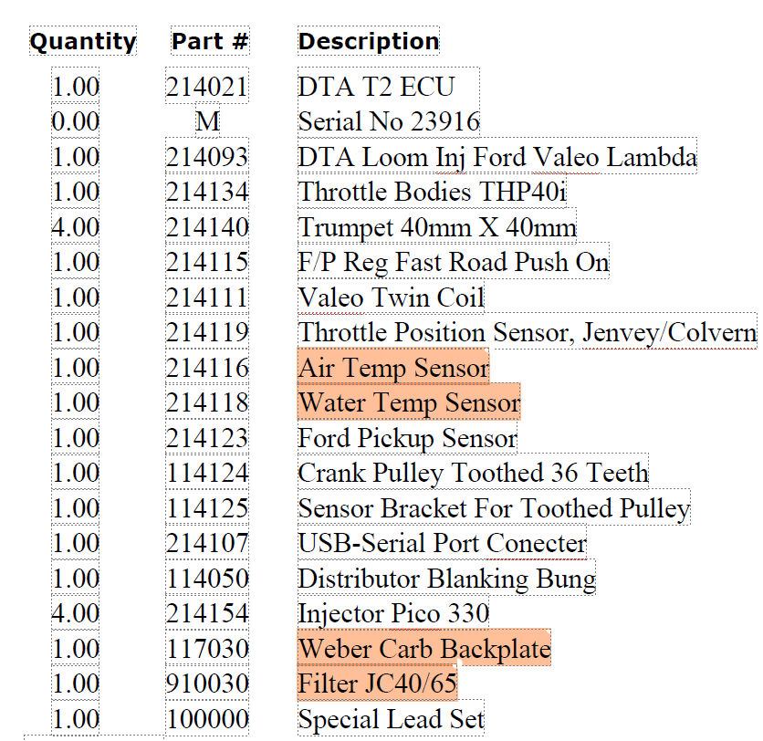
The kit that QED sells relies on a number of sensors to provide data to the ECU to allow it to correctly coordinate ignition and fuel injection functions. These are:
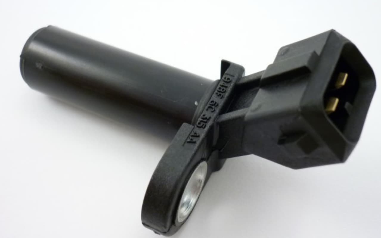
  1. The Crank Sensor:

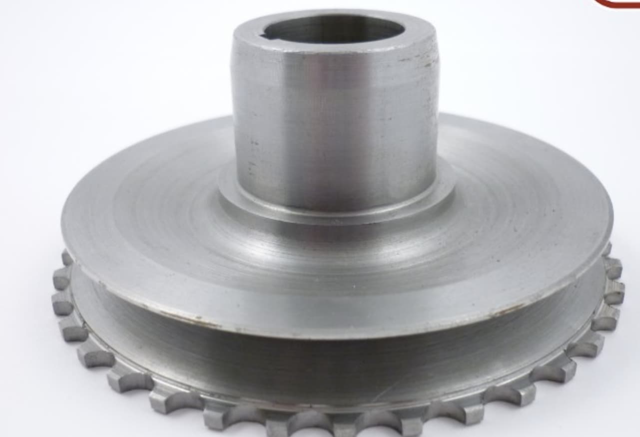
This provides perhaps the most important information for the ECU continuously telling it the position of the crank when the engine is running. This allows the ECU to understand when each piston is approaching its firing position so that fuel can be injected and spark applied. In the QED system the Crank sensor is combined with a new crank pulley which includes 36 machined teeth.

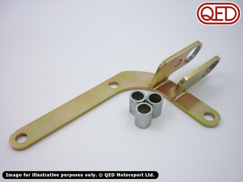
The movement of these teeth past the sensor as the engine rotates creates and regular pulse which provides information on the speed the engine is running. To provide position information for the crank one of the 36 teeth is removed and the position of that missing tooth with respect to the crank position is entered into the ECU software. In my case I used the mounting for the sensor supplied by QED.

(Interestingly my bracket did not include the spacers.. this might have made it easier to mount?)

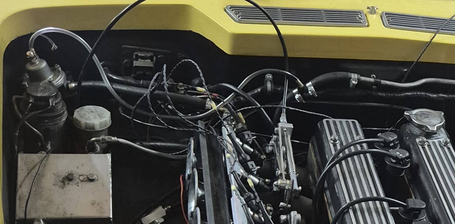
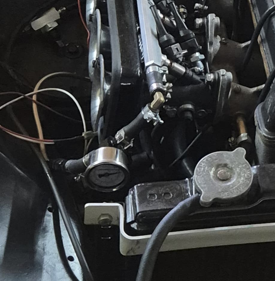
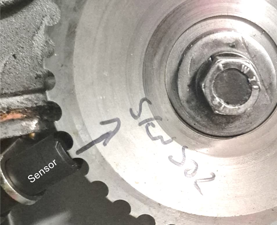
I removed the tooth that was adjacent to the tooth that lined up with the TDC mark on the engine. This meant that the tooth would pass the sensor 155 degrees before TDC. According to DTA, the ECU manufacturer it is useful that this is before TDC as I allows the ECU time to calculate optimum spark and injection before TDC is reached. I measured this offset using protractor which I created and printed out using protractor creation tool online (who’d have thought this would have exist). The mounting for the crank sensor is attached by some of the sump bolts. It looks like a nice bracket but I had to grind the mounting so it sat correctly on the sump flange. It is also important that the gap between the sensor and pulley is optimum. I checked the internet and it suggests between 0.5 and 1.5mm. I set mine to 1mm. Again although the bracket looks good you have to rig your own bolt and nut arrangement to adjust this (see photo). Once this is set up and when the ECU is wired and powered up you can use the oscilloscope function in the ECU software to check the signal from the sensor when you crank the engine. It will also tell you how many teeth on the pulley and how many are missing and even attempt to calculate the offset angle of the sensor.. nice

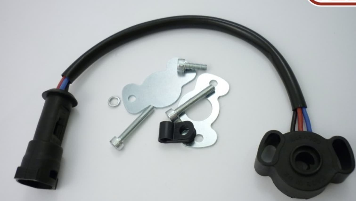
  1. Throttle position sensor (TPS):

This (as it says) measures the position of the throttle plates and is an essential data stream used by the ECU for calculating the correct fueling. QED supply a TPS which simply bolts onto the side of the throttle bodies. It can be fitted on either end of the throttle body assembly. I chose to place it at the back of the engine to simplify wiring. Again you can check its functioning by watching the TPS trace on the ECU software when you press the throttle. Once the engine is set up you also need to tell the ECU what closed and 100% open throttle looks like. This is done in the software by backing off the throttle stop and setting closed throttle (0% TPS) and then fully opening the throttles and setting open throttle (100% TPS). The TPS used by QED is actually supported specifically by the DTA ECU and the defaults were pretty much spot on for this. But probably best to set it yourself.

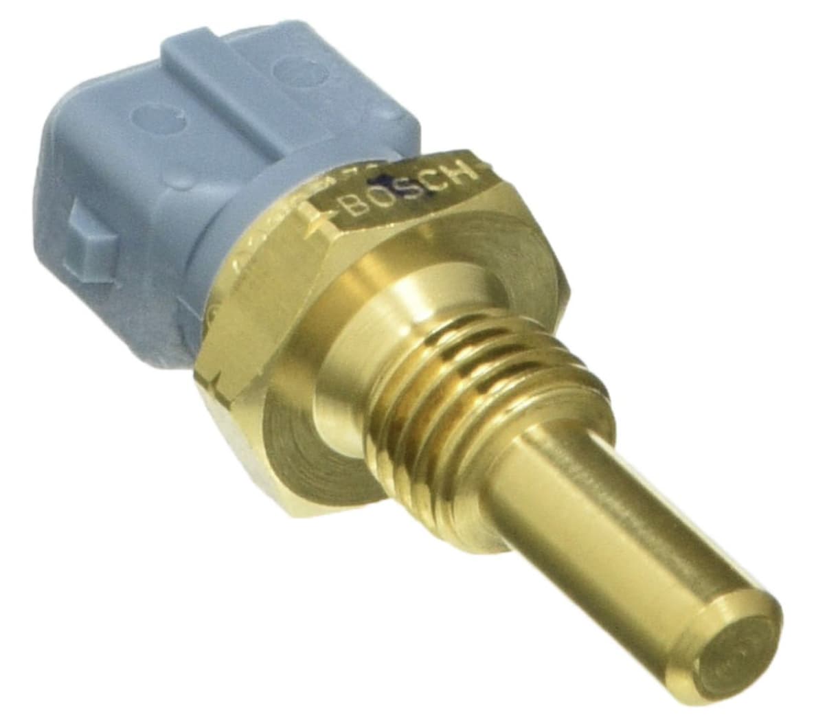
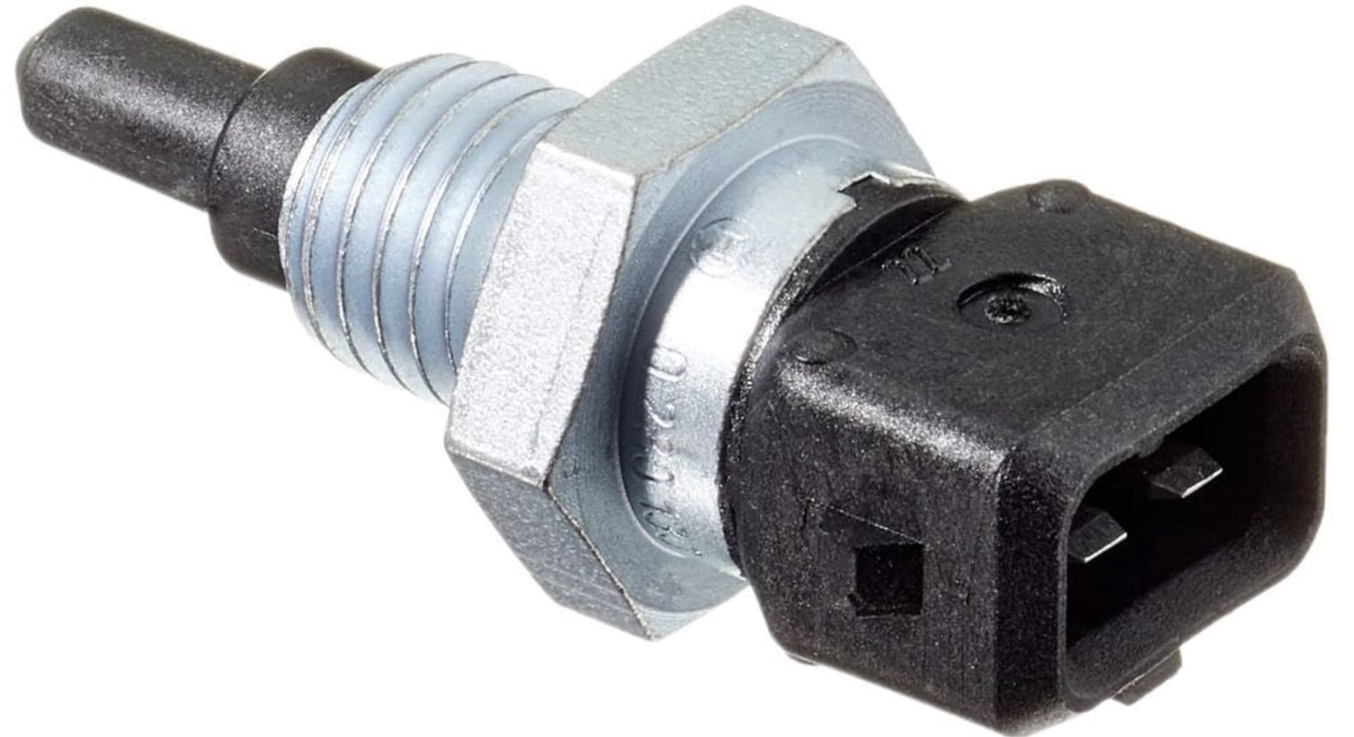
  1. Coolant Temperature sensor:

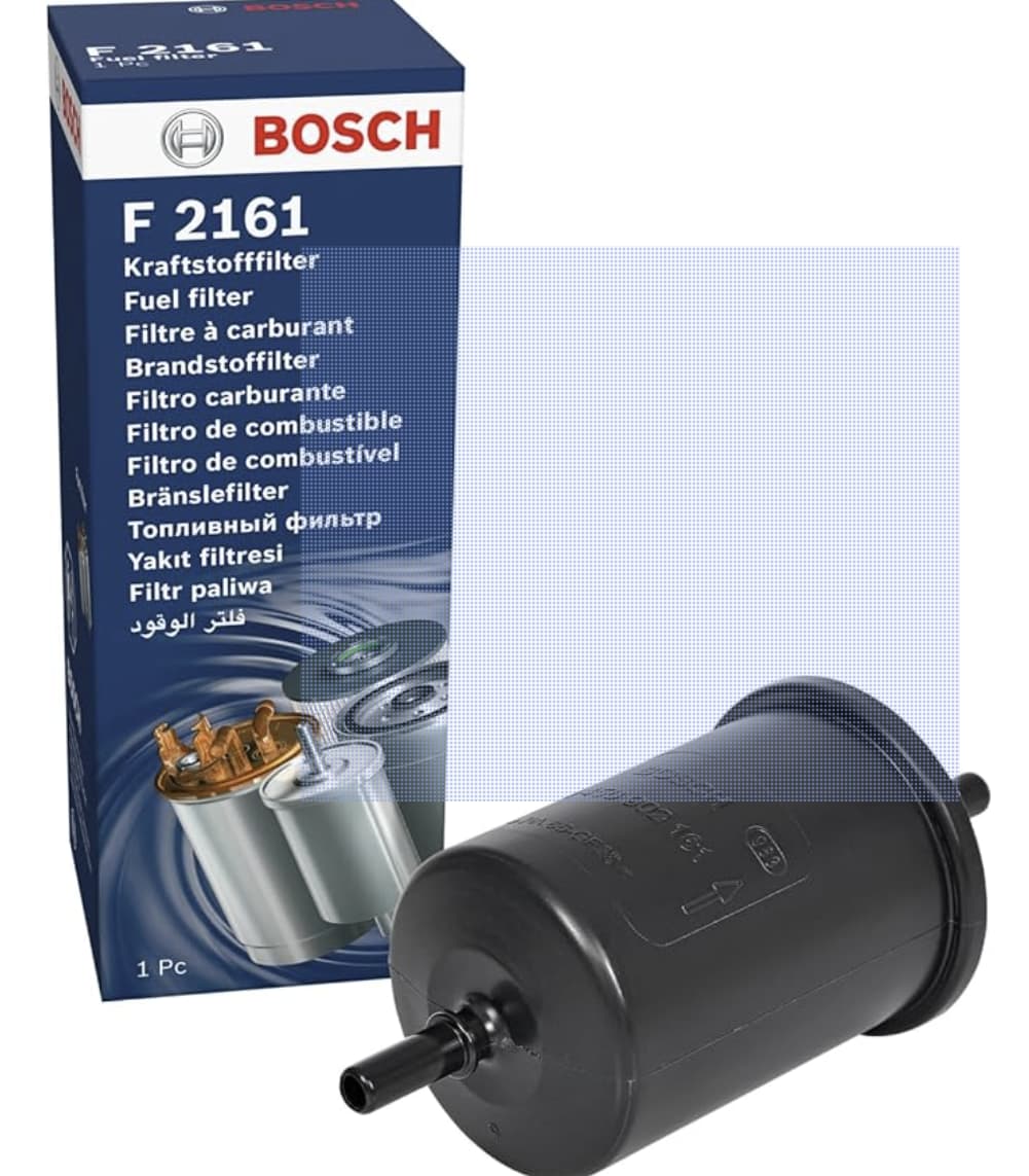
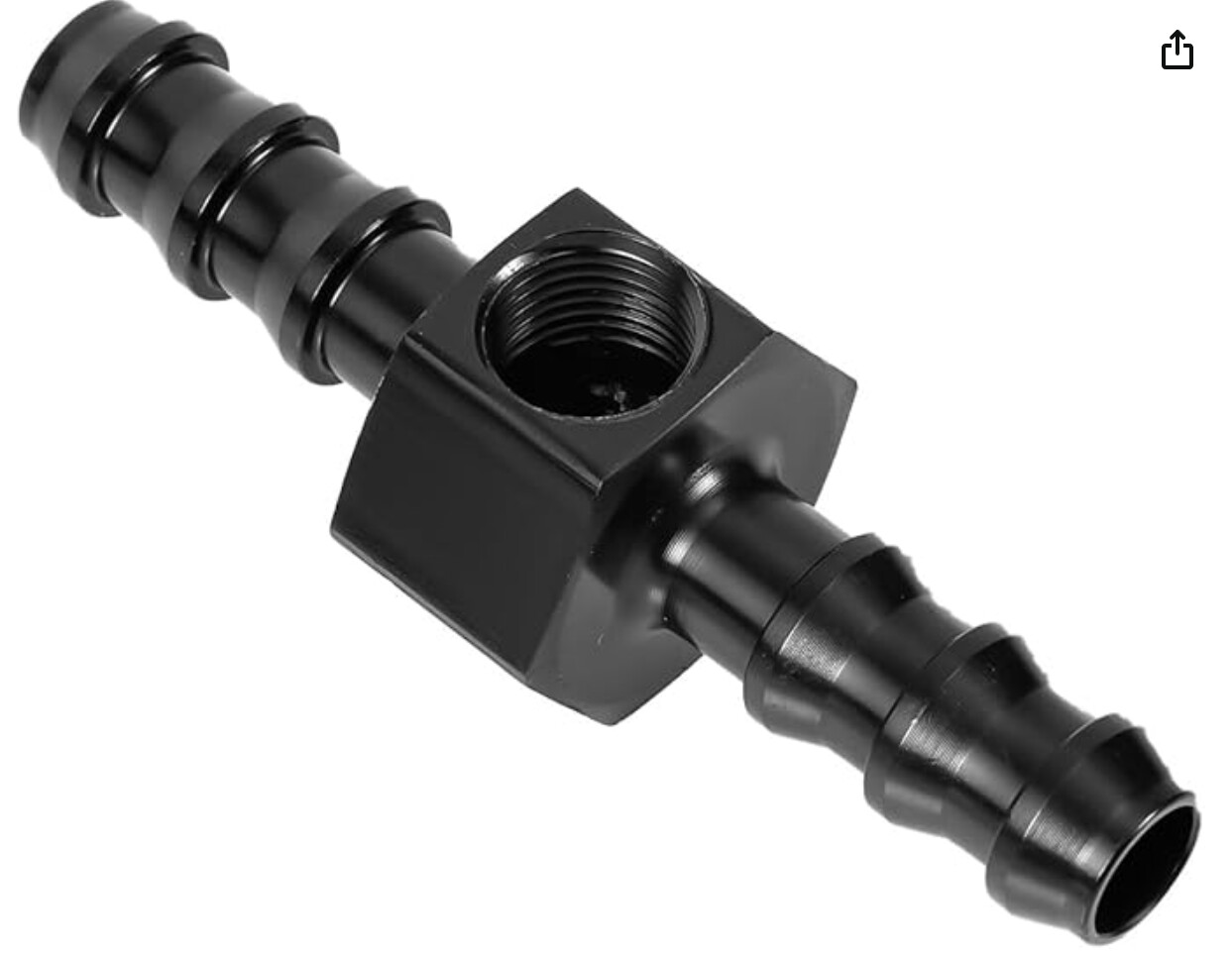
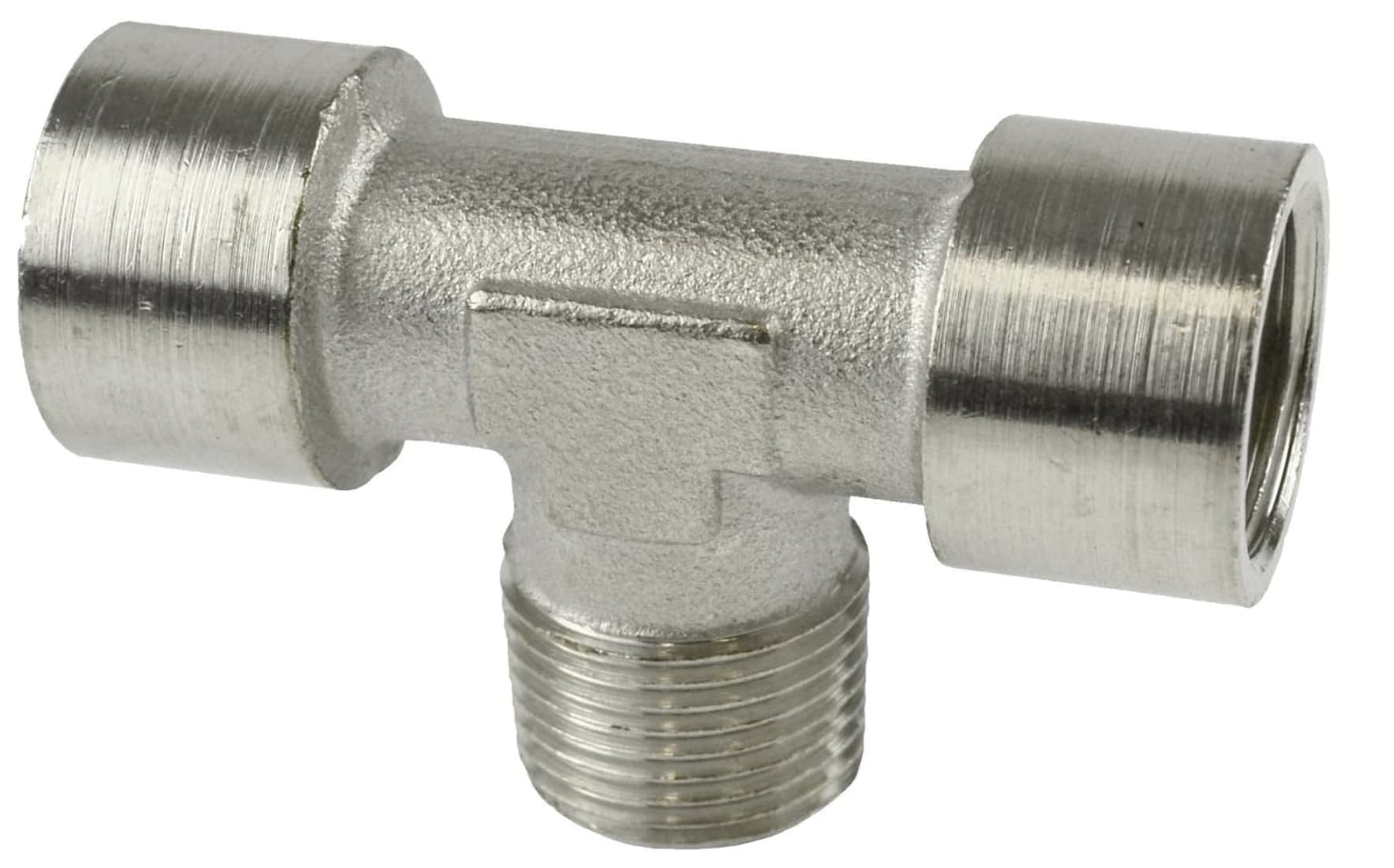
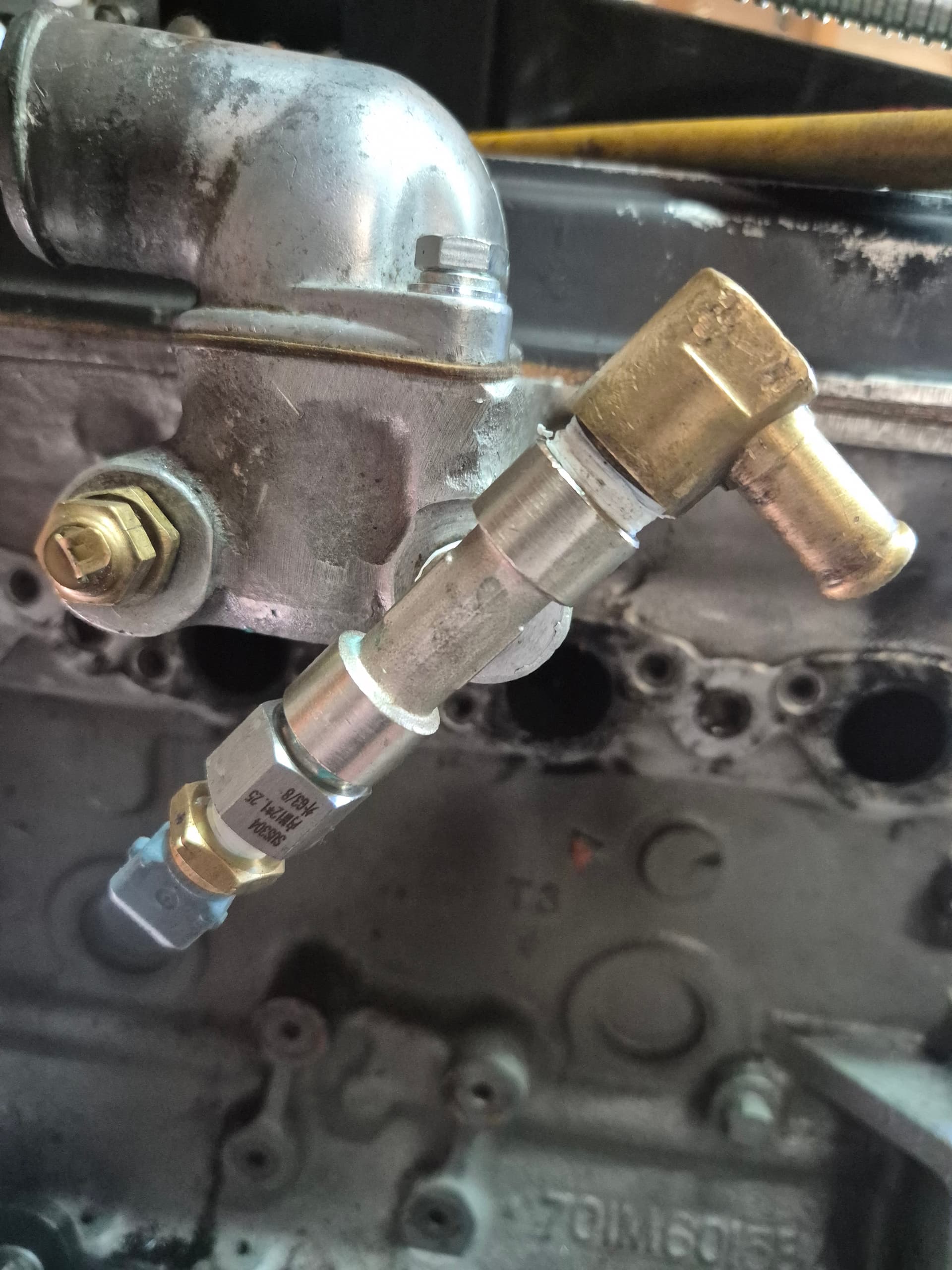
This (again as it says) measures the coolant temperature sensor. This is important information for the ECU (although not essential) which allows it to take into account engine temperature when calculating fueling and ignition. Perhaps the most important example of this use is at start up. The ECU does not have a choke cable so when the engine is cold it has to add some extra fuel. The sensor tells it just how cold. This means, unlike carbs, it can add more fuel if it is a mid-winter start and less when it is a mid-summer start. The data from the sensor can also be used to turn of the car if it overheats and perhaps more usefully can use it to control the rad fan. For this latter use you need to wire the ECU to the fan using a relay (the ECU will be damaged if it has to handle the current from the fan). The ECU should be wired into the ground side of the relay as it grounds its output when the temperature for turning on the fan is reached. It does not supply 12V to the relay. This is all useful stuff, but there are 2 issues with adding the sensor to the lotus engine. Firstly although the sensor supplied by QED will work it is not one of the presets for the ECU so you would have to calibrate it which would mean measuring it’s response to a range of temperatures from 0 to at least 120 degrees Celsius.. not fun. So I swapped it out for an equivalent Bosch sensor which is a preset (Bosch 0280130026 from Amazon). The second issue is that the Lotus Twincam does not have a designated place to put a modern temp sensor with a M12 thread. So I had to do some more plumbing. The natural place for the sensor is in the thermostat housing where the temp gauge sender is but I wanted to retain this. So instead it added a T-peice to the heater feed port. This is a single 3/8 " BSP male with 2 X 3/8" BSP Female from Amazon (Now I suspect the port in the thermostat is actuallt a tapered thread so should be 3/8 " BSPT but I could not find a T peice with this).

Into one female port I screwed the heater connection (Again I suspect this is actually BSPT).

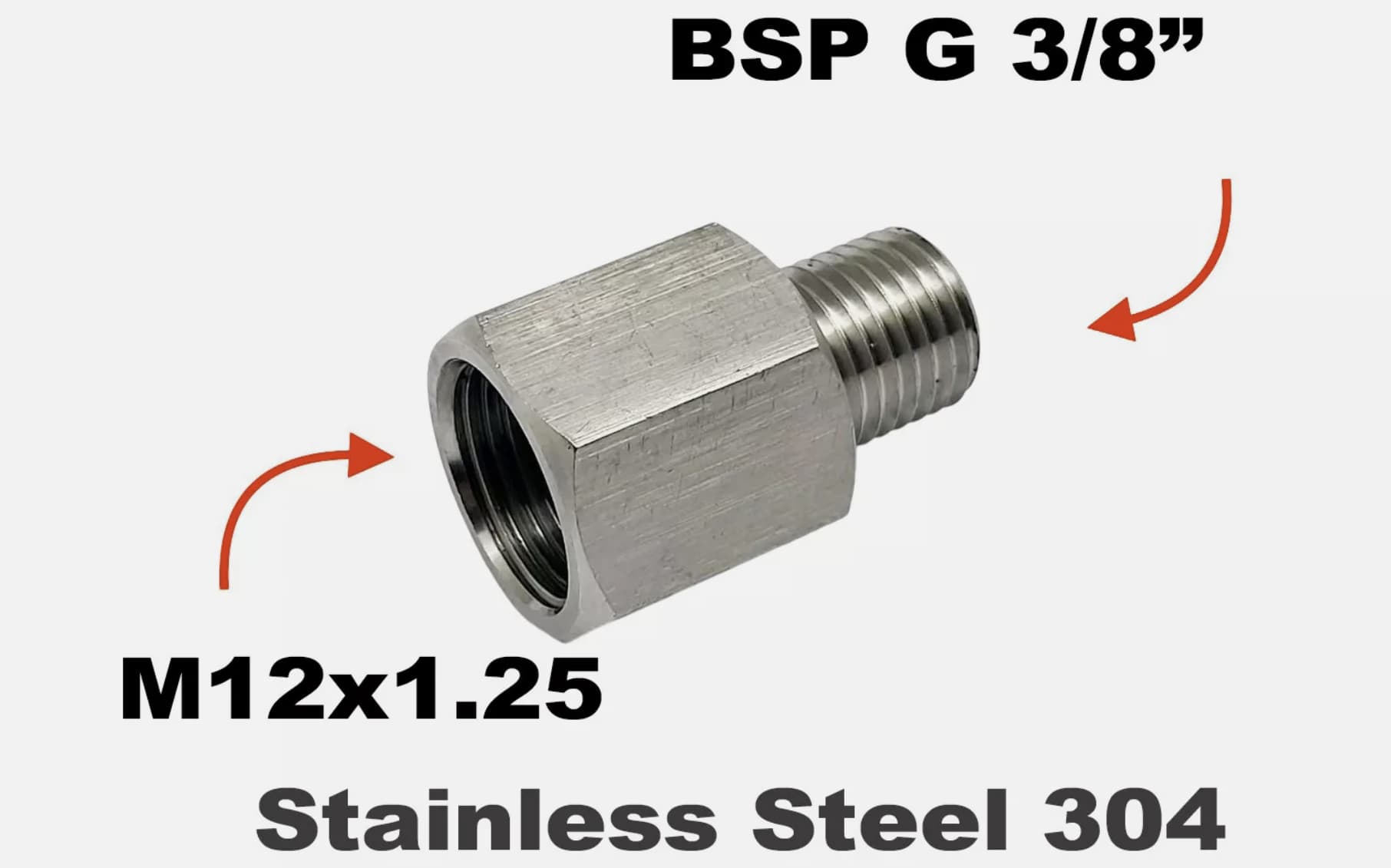
Into the other female port I screwed a 3/8 " BSP to M12 adapter which I found on Ebay.

This fitting worked but needed drilling out to allow the sensor tip to fit.

Air Temperature sensor:

An air temp sensor is also used to help the ECU calculate the correct amount of fuel. This sits in the airbox measuring the temp of the air entering the engine. It uses Boyles Law to calculate the density of the air entering the engine. Hot air is less dense so less fuel is required. Again I tossed the QED sensor as it was not a preset for the ECU and replaced it with Bosch 0 280 130 039 again from Amazon. I mounted this by drilling a hole in the airbox and using an M12 nut to secure the sensor.

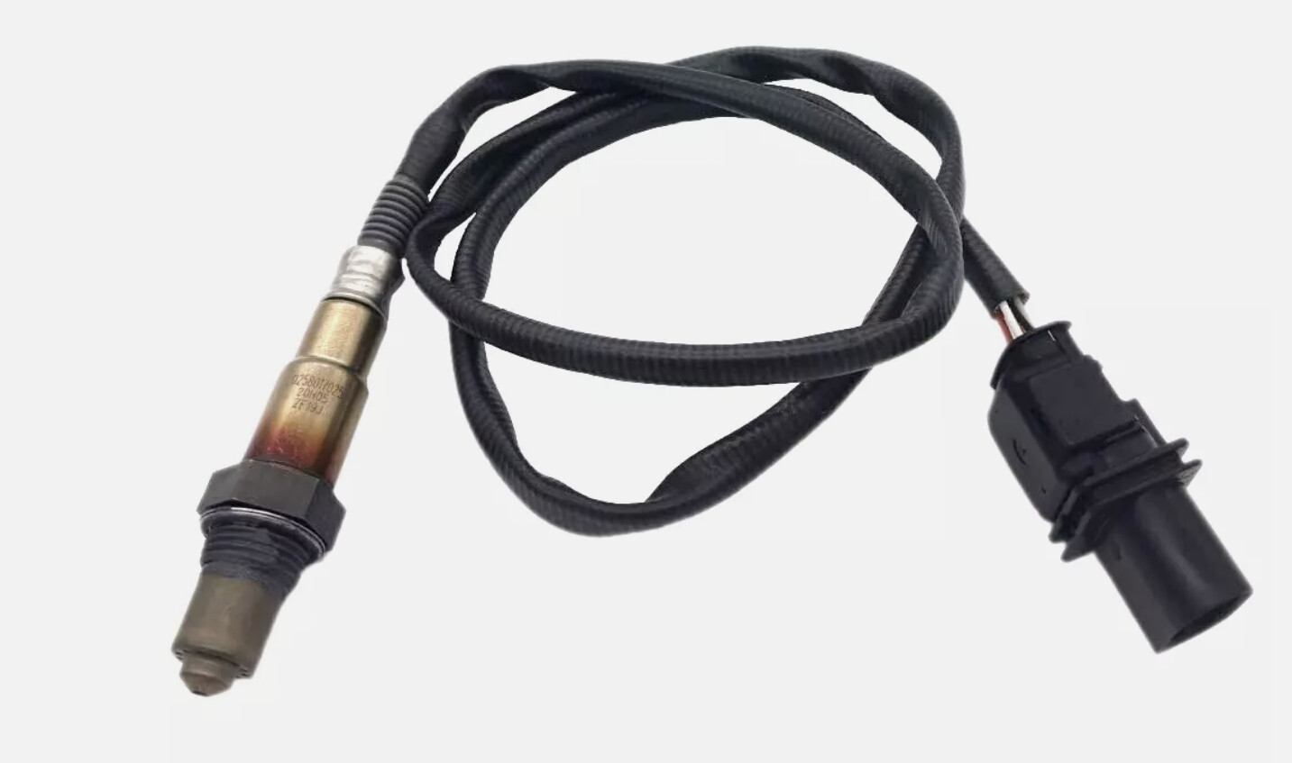
Air:fuel Ratio Sensor (optional):

A key way of checking whether an engine is running optimally is to monitor if all the fuel is being burnt. One way to do this is to use an Air:fuel ratio meter (sometimes called a lambda sensor) mounted in the exhaust system. This sensor either returns the Air:fuel ratio the engine is running at, 14.7:1 being the optimal for efficiency and closer to 12:1 for optimal performance or Lambda with a value of 1.0 being equivalent to 14.7:1. This data can be used by the ECU and the person tuning the car to check the mixture and is very helpful in developing the ECU map. It is 100% better than other gadgets like colourtune and plug colour. It is also a real time continuous measurement. You can run the ECU without this and if you map is spot on you’ll be fine. But it is useful to have one for 2 reasons: firstly for tuning and seconly because the ECU can use this data to help with idle mixture optimisation.
I chose to have one which meant I had to order a sub-loom from DTA which had to be added to the main plug going into the ECU. They have a handy youtube to show you how to do this.

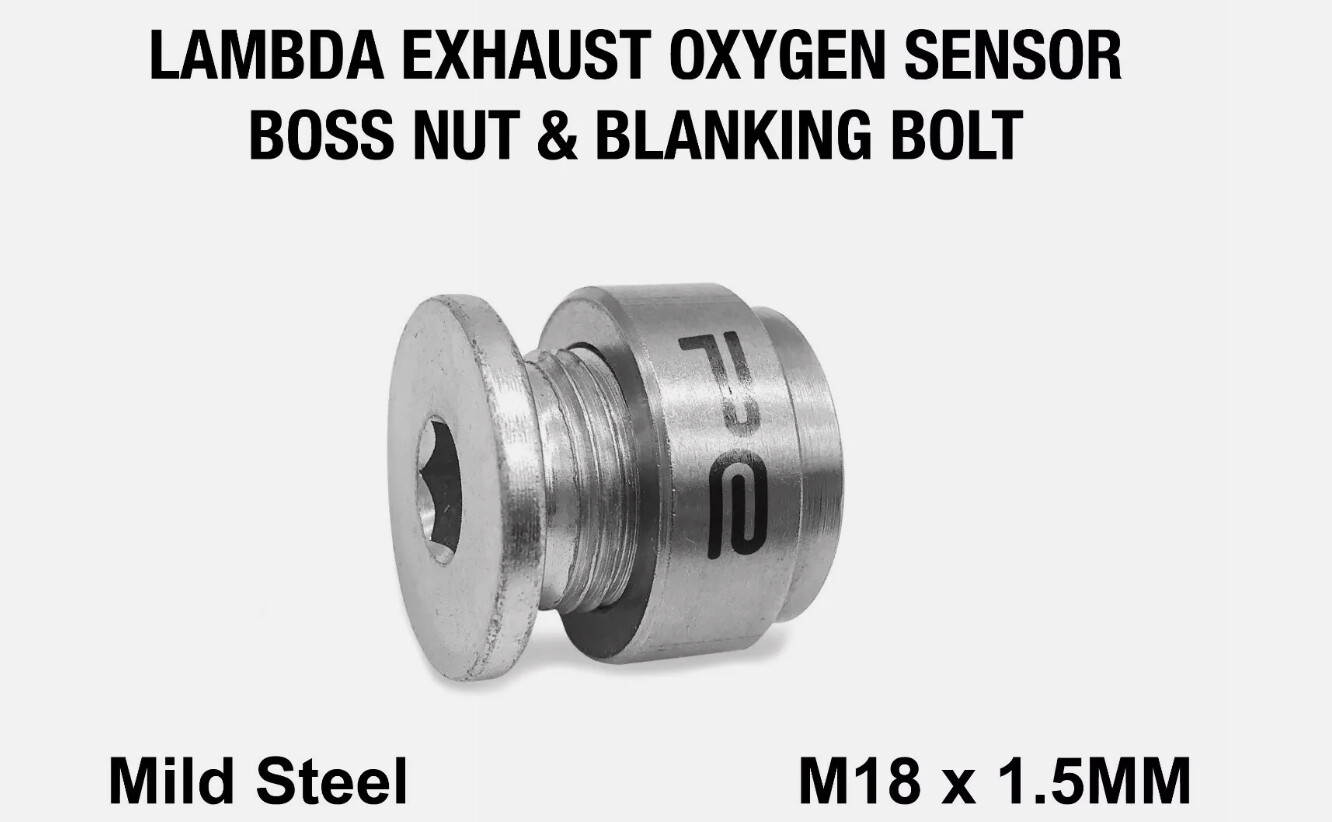
I then had to weld a Lambda probe boss into the exhaust.

I placed this downstream of the Y section of the exhaust so it sensed both pairs of cylinders and then it is just a case of wiring it in (Which requires you to wire a power supply for the sensor into a switched 12V (I used the redundant 12V coil supply) as well as the connections to the ECU.

Once all these sensors are installed and plugged into the ECU you can check they are working using the ECU diagnostics system. The only one you cannot check (as far as I can see) until the engine is running is the AFR as it seems to be programmed not to turn on until 10 seconds after the engine starts.. something to do with protecting the sensor.

「いいね!」 2

Thanks for posting the pictures.
Cheers
John

Hi Tim, useful info and good work!

(I’m doing something similar at the moment, you might have seen my engine thread that has now segued into efi conversion)

Cheers,

Will

「いいね!」 1


Refitted the trim panels. As you can see the plumbing has disappeared :slight_smile:

「いいね!」 2


Picture of the aetup i used for the temperature sender for thr efi