There are many posts about EFI in the forum where you can find information. Use the search function.
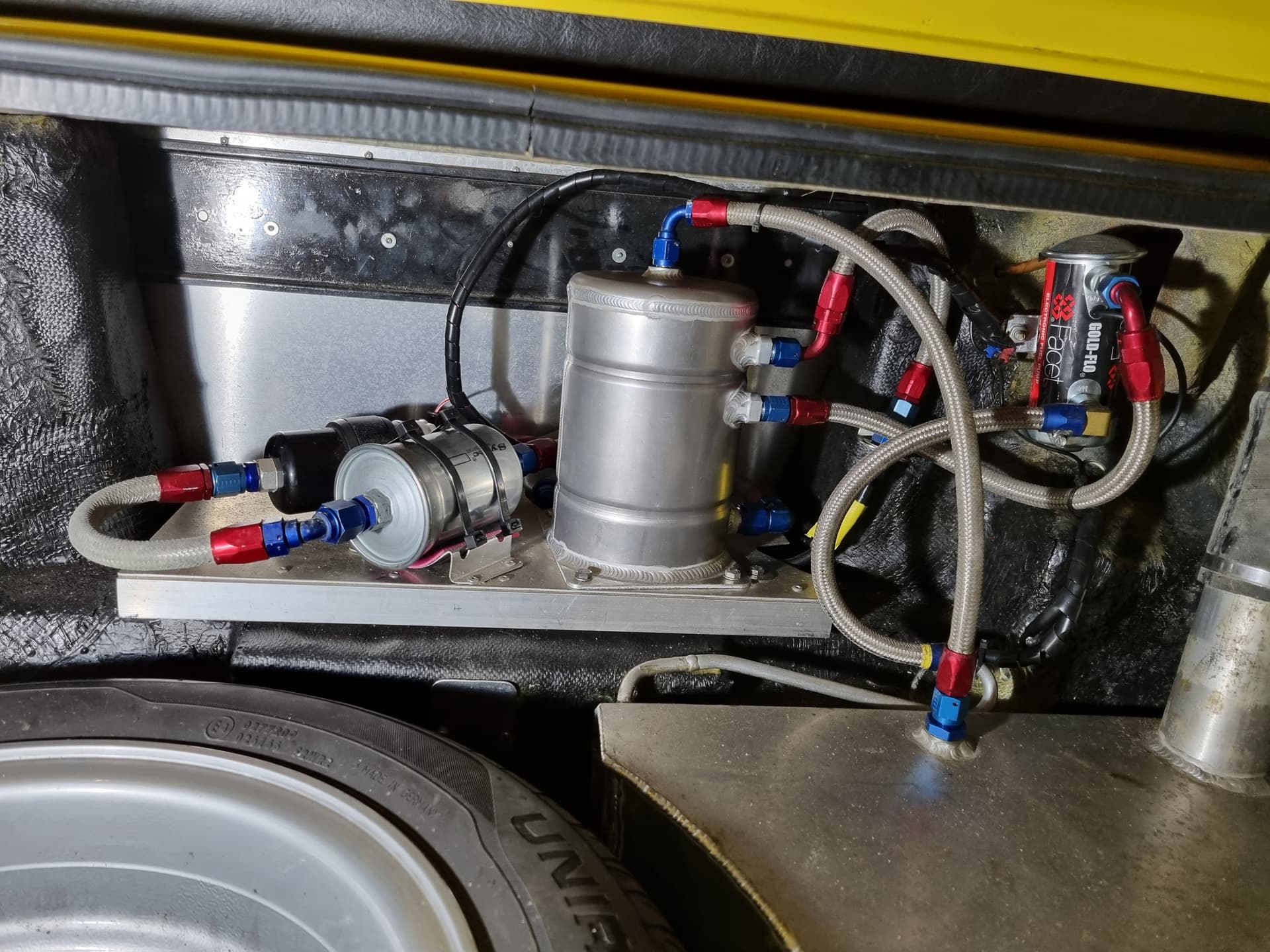
What I notice in your pictures:
1 The low-pressure pump wouldn’t be my first choice. Mine is a Pierburg. It’s quiet.
High-pressure pump – I would buy a Bosch pump. My Bosch 0 580 464 023 There are other good ones available today.
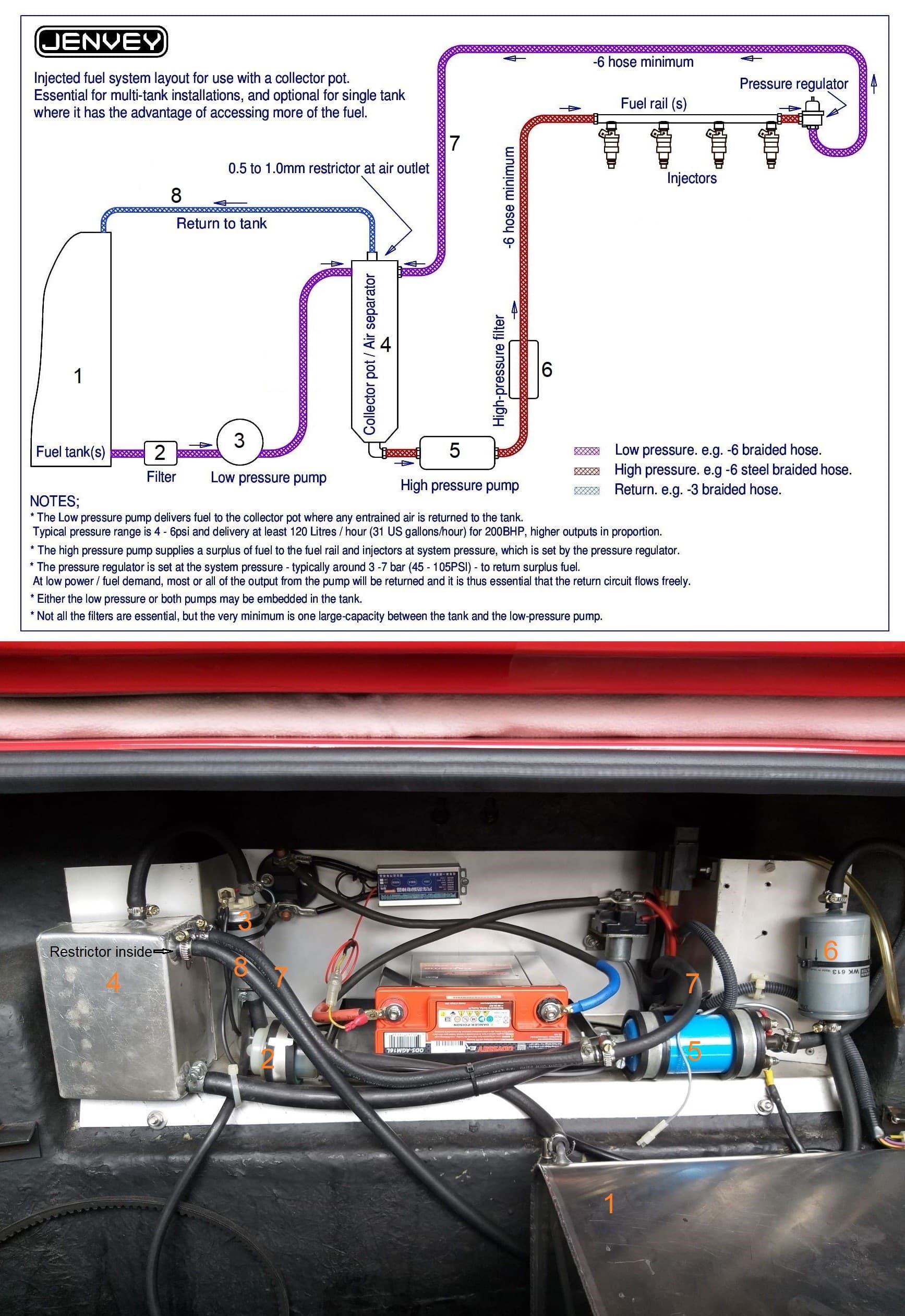
The high-pressure filter is incorrect; I think it’s a filter for the suction side. Hoses can slip off the connections. Alternatives: Opel 818500, BMW 13321256492, Mann WK 613, FIAT 4435144, etc. My Mann WK 613.
My fuel pressure regulator is a Bosch 0 280 160 214 (2.5 bar).
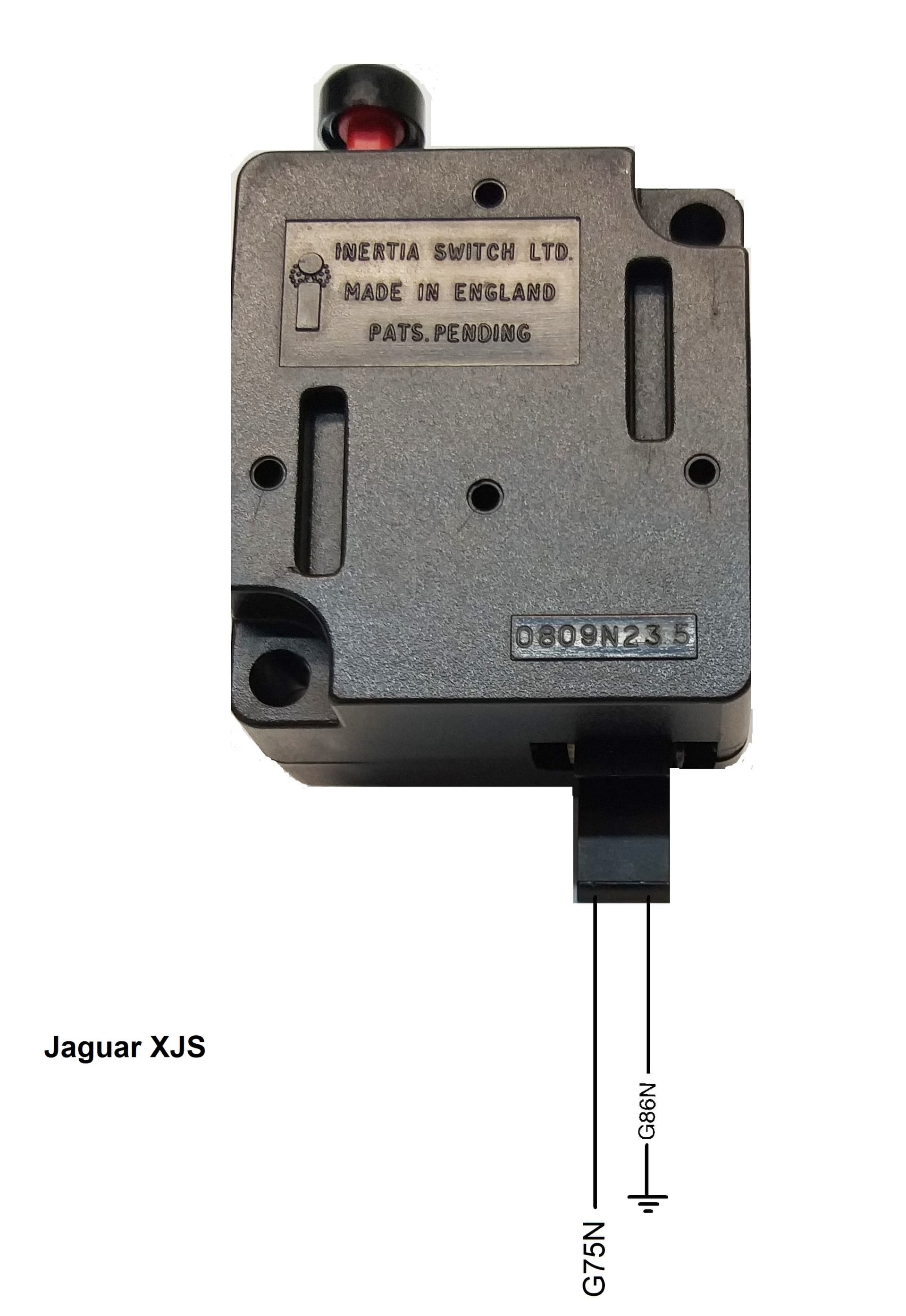
I also had the inertia switch in your picture installed, but I replaced it with the one in my picture
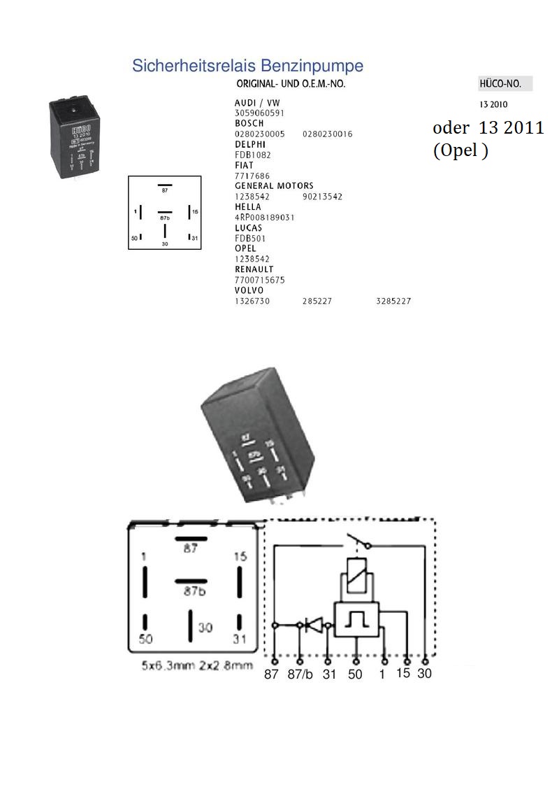
I can use it as a secret switch. I only switch the ground for my safety fuel pump relay.
This is a must for cars with electric pumps, even without EFI.
For example:
It doesn’t take an accident, but some kind of damage (leak) can cause a lot of fuel to spray around on the pressure side. I’ve experienced it myself, but not with my installation. If the engine is no longer running, it takes a certain amount of time until the car and the engine stop. If the ignition coil pulse is missing, the pumps shut down immediately; it can’t get any faster. Depending on the connection, the ECU also shuts down the pumps.
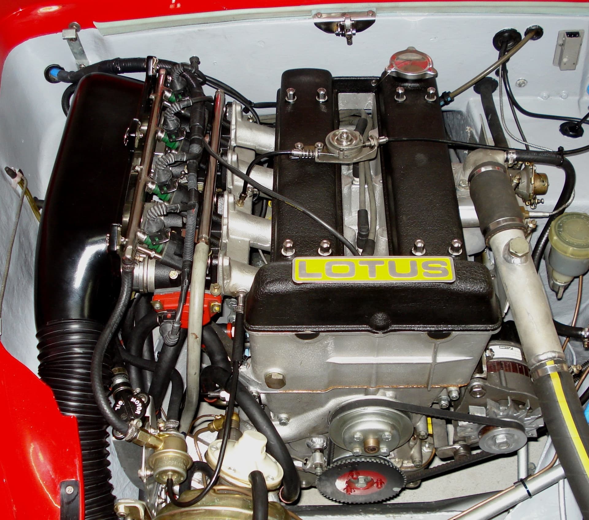
My installation, as later specified by Jenvey:
All in all, I drilled no more than 10 holes in the body.
Don’t be confused by Odyseey Battery, battery disconnect switch with manual and/or radio remote control, starter relay and main fuse.
I see that you are from the canton of Aargau and that your car is registered. How did it go with the vehicle registration office, which is known to be strict ?
For the stock Temp gauge, as I would like to use the housing also. If the OEM one could be removed and replaced with something that could serve 2 purposes (gauge and ECU) then it would be a BIG win.
Urs,
Nice details. Thanks. You are right about the filter, thanks.. i assumed (wrongly) that a filter labeled efi would be high pressure. Have now ordered a sytech filter which will fit.
Tim
Hello Stéphane
The vehicle inspection (MFK) in Aargau is very, very difficult.
The type number, which is entered in the vehicle registration document, is also very important. In the Aargau, even an incorrect steering wheel will prevent you from receiving the veteran registration. With our classic cars, it’s not quite as bad if the expert is a bit tolerant.
Nevertheless, I’m changing the EFI to carburetors. Everything is set up so that the swap will go quickly and smoothly.
I have just driven the Plus2 for a few hundred miles (some of it hard driving in North Wales and a fair bit of motorway) in one weekend and have learned a couple of things about my fuel injection set up. And also about the car generally, but that can be a different post.
The main EFI one is that the fuel can get very very hot in the swirl pot. Too hot to touch the swirl pot hot. This is not good for the fuel pump(s). I noticed it after the high pressure pump got very noisy. Also there was no fuel being returned to the tank as it must have been vaporising and stopping the Facet lifter pump from working. So I removed the 1mm restrictor and once things had cooled down there was a strong flow back into the main tank. So that would be enough flow to keep the swirl pot cool which turned out to be the case. It was certainly not true with the 1mm restrictor in place.
Sadly though while on the M54 (yesterday) the car exhibited fuel starvation again. Thankfully we got to the last layby on that stretch and were recovered from there (bit of an ordeal). The Facet pump was running, but delivering no fuel back to the main tank. Fuel was not hot but the pump had clearly failed.
I am now proposing to use a large carburettor type fuel filter off the main tank and have that gravity feed an eternal 044type external HP fuel pump with the return directly to the main tank. So the same as an in tank system but with the pump external and the big fuel filter as a reservoir.
Berni
If it helps, this is my set up. I have no restrictors in the fuel system and the fuel filter I use is a Sytec motorsport directional type. It is positioned before the pump as advised by the technical guru at Glencoe who I find very helpful.
I was told that if the pump is starved of fuel for more than 10 seconds, it will overheat and fail so I have separated the pump circuits and switching so that I can turn on the lifter pump and prime the swirl pot before turning on the high pressure pump.
One of my jobs for the winter is to change fuel tank and use a gravity to feed the high pressure pump rather than a lifter…
Good luck
Gavin
I have been doing quite a lot of experimentation, and did try using an unrestricted (no filter) gravity feed rather than a lifter pump. The issue I had is that on the breather from the swirl pot (which you need in case any air gets in there) will not function if it has any fuel in it (which it will). My return is quite high though (above the surface of the fuel) so the pressure from the gravity feed is insufficient to push the fuel out of the swirl pot breather. The next thing I found is that if you return the fuel to the main tank then even with an enthusiastic lifter pump it will not keep up with the HP pump and so the swirl pot will drain. So the return from the fuel rail has to go to the swirl pot. I did not want this originally because of the fuel heating issue I had previously, but hopefully the return from the swirl pot to the main tank will be at a sufficient rate (governed and powered by the lifter pump) to keep the fuel turnover in the swirl pot high enough to dissipate any significant heat buildup.
So to recap fuel into swirlpot via lifter, HP pump (lives in swirlpot) to fuel rail, return from fuel rail to swirlpot, unrestricted line from swirlpot back to main tank.
Lifter pump is noisy but will be soundproofing that.
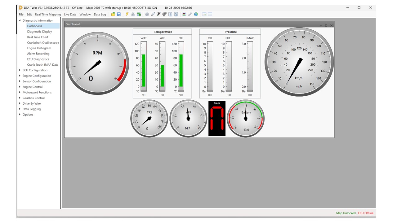
I have now started mapping the DTA EFI system on my bigvalve twincam so I thought I would include some details on this thread to help anyone else going down the same route. To begin with the key think is to get an overview of the TWin software supplied by DTA to program the T2 DTA-Fast ECU. The software is downloaded from the DTA site and installs reasonably easily. It is a little slow to start up and can be run independently from the ECU or interactively with the ECU if connected with a USB and the ECU powered up. In connected mode you can read real time data from the ECU, do some logging and modify parameters live. Whereas the independent mode allows you to get to know the software without being connected to the ECU. You can also make changes to the map and save it and then update the ECU settings when you connect, although this can be a little risky as it is easy to loose your place in the ECU optimization process if you are not watching how ECU setting changes alters engine performance. Once the software fires up and you choose T2 and work non-interactively you get the following screen:
Along the top are various menus to access settings and some short cut keys. Down the side are all the settings that you can change in sections. In the centre is the “dashboard” which shows most of the info you would see on a normal car dashboard (including the Air:fuel Ratio and the Throttle Position sensor output). It should be noted that you will not see anything on the speedometer as there is no sensor for this on the Twincam.
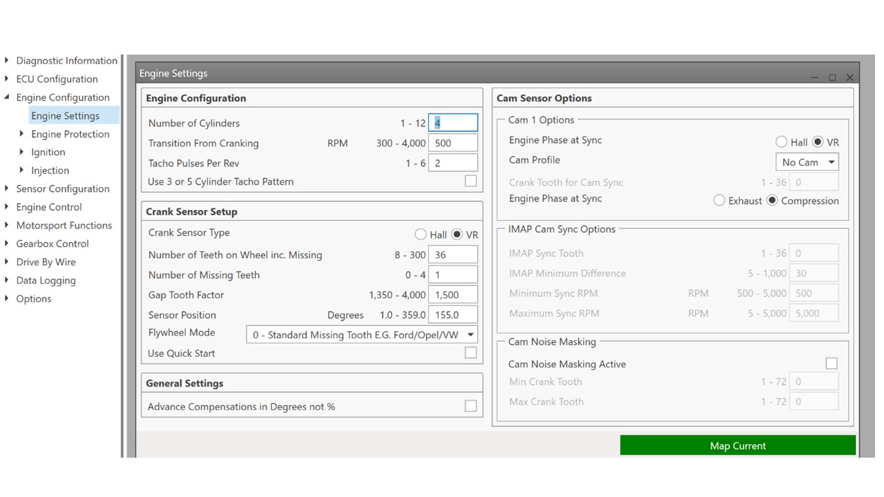
You can select extra windows showing other data from the menus on the top or down the left. To begin setting up the ECU you need to pull up the Engine Settings sub-menu in the Engine Configuration menu.
In this window you can begin to setup the ECU with the engine settings, like number of cylinders and crank trigger settings. These settings are for the QED setup but you will need to confirm the Sensor position with respect to your engine. As can be seen in my details on crank sensor setup I chose not to use the QED supplied spacers. I would ignore the Tacho Pulses per Rev here as I have not setup the Tacho feed yet. The Transition from cranking rpm is important to enable the transition from cranking to running (the ECU uses different timing settings for these 2 phases). Ignore the cam settings as we do not use this for the twincam.
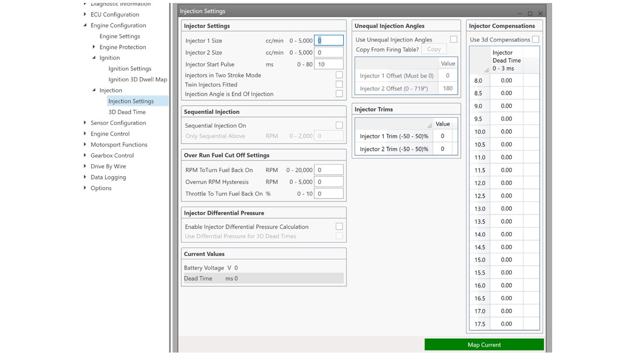
Which just needs the injector start pulse setting. This is a pulse of fuel that is injected before start to wet the dry inlet manifold walls. To begin just try a number.. you will optimize later to help with starting. The Size of the injectors can be added later. It is not used as far as I can see in any calculations.
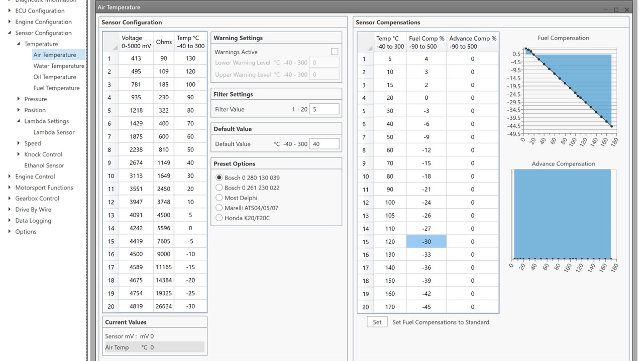
Now we can move onto sensors.. Air Temperature first. Here you need to select the correct sensor. The one here is for the air sensor detailed in my thread. No need to touch anything else at this point. Water temperature, again select the temperature
sender type (again in this case this is the one detailed in my previous write up).
In both of these you can see you can set a default value which is what the ECU will use if the sensor malfunctions for some reason. You can also add temperature dependent modifications to fueling based on air/water temperatures. No need to touch these yet.
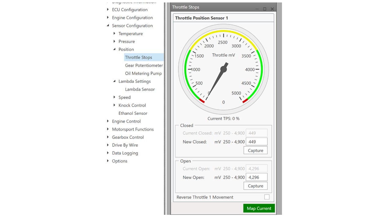
Next we select Throttle stops under the Position sub menu. This allows you to tell the ECU the voltage it should expect from a fully closed and fully open throttle. To set this, back off the idle control screw on the throttle body until it is not touching the throttle arm and then set this as “closed”. Then push the throttle until it is fully open and set this as “open”. You should see the throttle mv change when you press the throttle. If it does not change then your sensor has an issue.
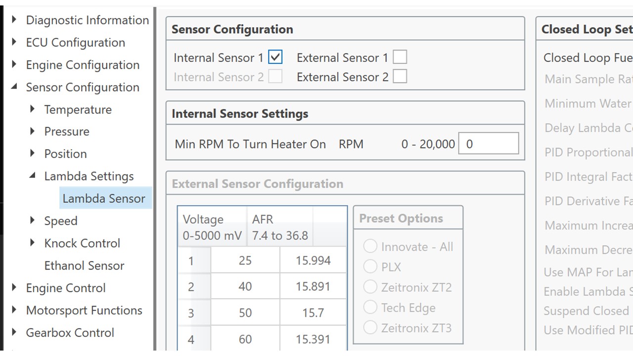
Finally you need to set up the AFR sensor if you are using one. This is initially the simple task of clicking on “internal Sensor” in the Lambda sensor menu.
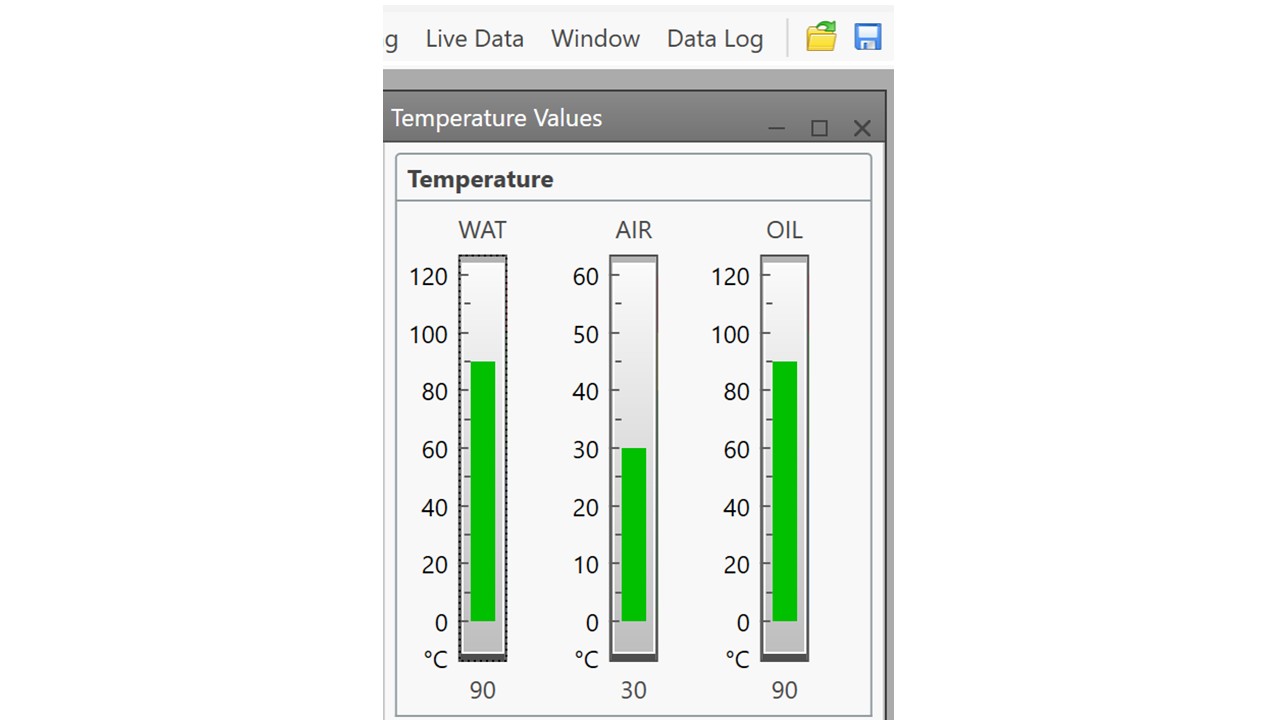
Obviously the temperature outputs should match the ambient temperature if the engine has not been started. NB: The oil temperature means nothing unless you have fitted an oil temperature gauge. For these data shown here the engine has been running (hence the elevated water temperature and air temperature (sensing the under bonnet temperature which is clearly above normal air temperature). If you find any of the sensors are not giving the correct information you check they are connected. This can be accessed by selecting Diagnostic display sub menu in the Diagnostics Display menu.
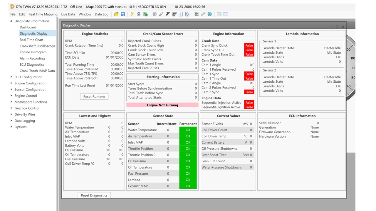
The Diagnostics Display shows Sensor states showing that they are all OK. You also get information on some of the engine statistics (including how long the ECU has been on). More important you can also see crank sensor errors which can be useful if you struggle to get the ECU to syncronise with the engine rotations using the crank trigger. Finally of use is the Starting Information which provides information on the number of failures to start.
Once all these parts are setup and transferred to the ECU (this requires you to be connected to the ECU with it powered up and then press F4 to transfer information to the ECU), you can check the synchronization of the engine with the ECU. This is well covered in the DTA-FAST Win-T manual. My process was to select the Crankshaft Oscilloscope from the Diagnostic Information menu. I then removed the plugs except the one in cylinder 1 (nearest the front) and turned the engine over on the starter after pressing the “gather” button (One issue I had was this was hidden as the window was larger than my laptop screen and it took a while to realise I needed to scroll down ). Once the engine turns over you should see a trace that shows the pulses from the crank trigger, including the gap from the missing tooth. You also see that the amplitude of the peaks of each pulse rise and fall slowly over multiple peaks. This is related to the change in speed of the crank induced by the compression on cylinder number 1. From these signals combined the gap between the missing tooth and TDC can be determined (see the DTA manual) and entered into “sensor position” space in the Engine Configuration Menu.
Once this is all setup replace the plugs (don’t want things falling into the engine!).
Hoping to spend next weekend doing some initial mapping based on one sent to me by QED. it is good enough to get the engine running and drive too and from the local petrol station but seems too rich in places and has no transient enrichment setup. So more to come hopefully.
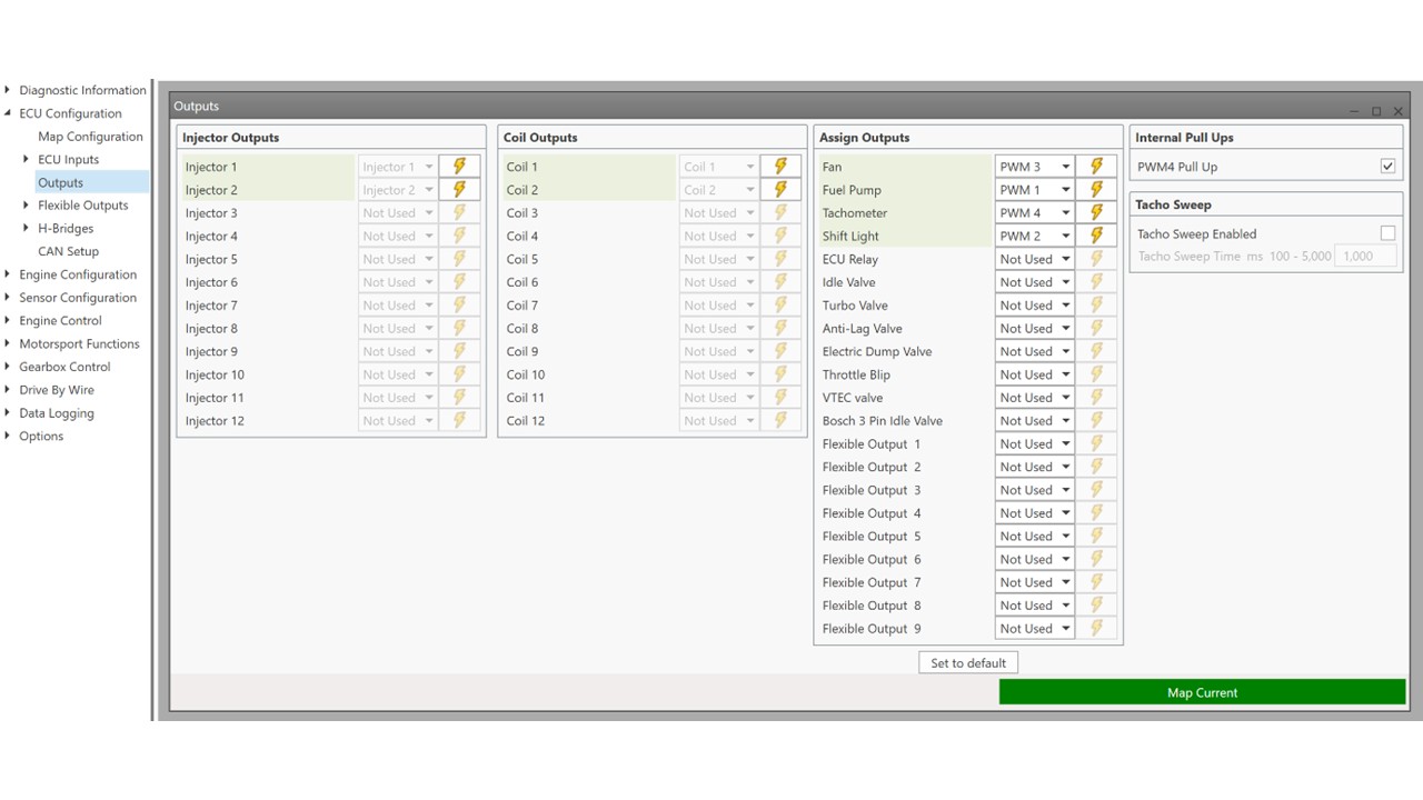
The above section sent up the sensors feeding information to the ECU. The next step is to check the outputs. In this case, injectors and the coil pack outputs to the plugs. Handily the T-Win software allows you to trigger these manually. This option is found in the Outputs window in the ECU configuration Menu.
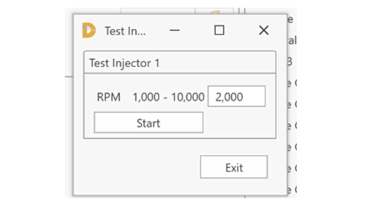
To test the injectors select the “lightening icon” on the relevant injector (NB there are only 2 on the T2 as they are fired in 2 pairs of 2. This opens the following window.
Clicking on start makes the injector cycle at the 2000 injections per second (NB: do not do this with the fuel pump running as this will flood the cylinders with Fuel). If all is good you should hear the relevant injectors ticking. Now do the same for the other injectors. If they also tick all is good. If not, check the wiring.
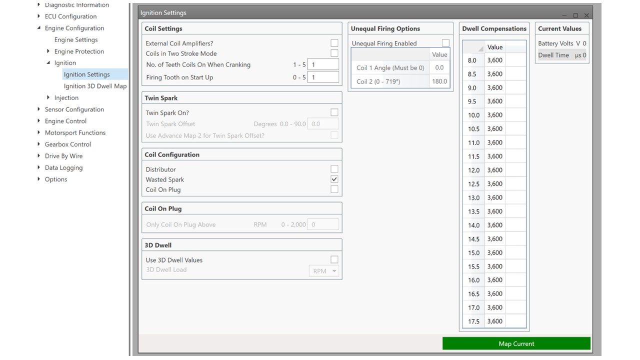
Next for the ignition, place your ignition timing light onto one of the HT leads and select the “lightening” symbol and then the “start” button. If you have selected the correct lead and all wiring is good the timing light should flash. If it doesn’t flash try another lead. Mark those leads that flash (it should be 2 of the 4) with a “1”. If no flashes are seen from the timing light then you have a wiring issue. If they do flash, do the same for Coil 2. In theory the other 2 leads should leads to cause the timing light to flash (mark these as “2”)
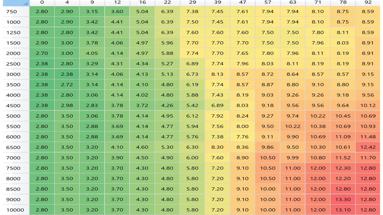
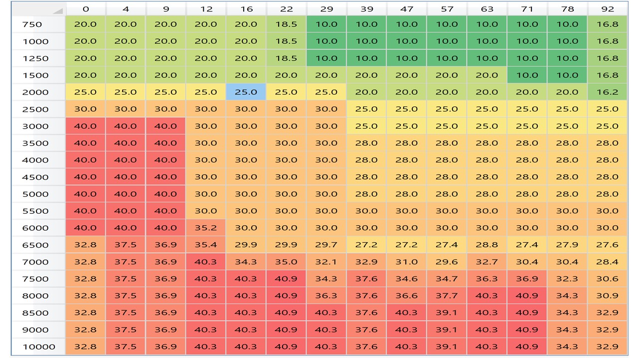
Now you need to set up the ignition and fueling map. These can be accessed by selecting Main Fuel Map and Main Ignition Map in Engine Control. The fuel map relates the number of milliseconds the injectors are open at different engine speeds and throttle opening (%).
Initial maps can be obtained from QED but be aware that using them will alter all the sensor settings so you will have to go through the process of setting up the sensors as we have done in the earlier steps.. The maps shown here are ones that I arrived at for my BigValve after a couple of days of playing on the road.