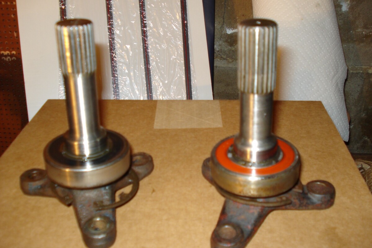
My S3 has a loud differential whine so I purchased a used 3.55 unit to install in its place. Since I must replace the pinion flange anyway, I decided to split the case and have a looksee. The stub axles are different from each other but both have the reduced shaft. The spline lengths are also different (see pictures). The internal gears appear excellent however the wear pattern on the crown wheel appears to be centered towards the toe which suggests moving it away from the pinion gear. This will also increase pinion to crown wheel backlash. If the present backlash is acceptable I may just throw it all back together and hope for the best. If not I guess I will go through the whole setup process.
Tomorrow I will try to get a better picture of the wear pattern.
I want to order bearings and seals from bearingkits.co.uk but they require a forwarding service to ship. Has anyone in the US used Forward2me or a similar forwarding service? Are the costs reasonable? Thanks
Chris
Chris, I ordered all my diff bearings from TTR and they arranged everything. It’s all seamless and you get an invoice from the forwarding service after delivery for fees and taxes. It was cheaper than I thought.
Glen
Thanks for the info on TTR. Do you remember what your stub axles looked like? Similar to one of the two styles I am showing? I am thinking one may be original Lotus and the other an upgrade or aftermarket unit.
Later
Chris
Chris, I ordered new axle stubs from TTR as I was increasing the Twin Cam engine HP to about 150HP +. The original axle stubs for my S1 not up to the increase in torque.
See my S1 rebuild post. Lots of detail about the diff and replacing the stub axles and bearings.
I think that both of your diff output shafts are original Lotus parts. The one you have marked “L” is a later type that was part of a fail safe measure that Lotus added to limit motion of the intermediate shaft in the event of a Rotoflex failure. The diff output and outboard shafts had pins welded at the centerlines and the intermediate shafts had pieces of round tube welded at both ends. When assembled the pins in the inner and outer shafts fit into the tube sections on the modified intermediate shafts. There was plenty of clearance between the pins and tubes to prevent limitation of normal flexure of the Rotoflex joints. However upon failure of a Rotoflex this system prevented uncontrolled flailing of the intermediate shaft. The pin has been cut off on your example. many owners cut these pins off when fitting CV joint axle conversions.
Agree the L shaft appears to have had the pin cut off. I have always seen the ones with pins to have the straight shaft the same OD as the splines and with the longer splines. It may be just the photo but have a close look at the R shaft as from the photo the splines appear to have a very slight twist about 2/3 of the way from the top where they twist at the exit from the diff centre.
On closer inspection it’s obvious the pin has been cut off the left axle. Also the right axle is indeed twisted exactly as Rohan points suggests.
Question: Can the pinion to crown wheel backlash be accurately checked with a dial indicator placed against a crown wheel tooth and rocking it back and forth…
Thanks to all so for your valuable help.
Chris
Yes that’s how I did it. With a magnetic stand and long 150mm probe on the dial indicator it was easy to set it up tangentially to the crown wheel and measure the backlash on a tooth at the outer edge.
It is a common bearing, one cross-reference is NTN 6206C3. They should be available from any decent bearing supply house. Why not just buy from one of the good US suppliers such as RD Enterprises? NTN 6203C3 Bearing Data Sheet.pdf (58.2 KB)
The original Ford diff assembly bearings were Timken. I would try to reuse those at least for the pinion if you are going to rebuild using the same pinion shim as their assembled height should be the same. This of course assumes the diff your rebuilding still has the original Timken bearings.
The diff carrier and output shaft bearings are less critical in assembled dimensions and any good bearing supply company should be able to supply them in an equivalent to the originals from a good name brand.
Rohan,
Thanks for filling in where my brain went to sleep! I saw the comment amount buying bearings under the images of the diff output shafts. I forgot that the real question was about rebuilding the differential itself.
I like Ray and will continue to buy parts from him but the price he quoted me for pinion bearings were over three times the cost from other suppliers. If I replace pinion bearings then I will also use a new crush washer and reset pinion depth. What I don’t understand about using the crush washer is, If it takes so much force to collapse the washer, how do you know you when to stop? Do you tighten until it won’t crush anymore and then back off to get the 9-11 inch pounds? Does the 35 ft. pounds of torque on the pinion flange nut become irrelevant?
Thanks
Chris
setting pinion depth
Would it be possible to set pinion depth using the following method?
Remove spider gears and install a machined shaft through the two carrier bearings and using an inside micrometer measure between shaft and pinion bearing seat in the diff case? Adding half the shaft diameter should give center of crown wheel distance.
Chris, you tighten the pinion nut thus crushing the spacer, after some crushing the taper roller bearings will start to contact each other… This is the critical stage! As you carry on tightening and crushing you will be forcing the taper bearings together and they will start to bind up/become tight to turn, this is what you will measure as preload by the force needed to rotate the pinion.
So, just after you know the bearings have touched (no end float on the pinion shaft) nip it up a bit more, remove the tooling ( wrench & holding bar) and check the preload torque… Not enough? Nip it a bit more and test again…
If you go too far don’t leave as you will likely knacker the bearings in a short time! Oh and don’t back the pinion nut off if you go too far, pull the old spacer out, replace it and do it again! Dont forget you can test the pinion/crown wheel depth without the spacer, just use a non locking nut and gently do it up to get a bit of preload.
Talking of preload, you have breakaway preload, the force needed to get the pinion turning and rotating preload, the force needed to keep the pinion rotaing at about 1 rev per second, for the latter you would need a special gauge though. Do you know what the spec is?
Is that really a twist on the R shaft? Looks more like a wear mark from the splines in the gear to me, but the picture is not very clear?
In my S1 parts manual the bearing description is “LJ 30 WSRR Ransom and Marles or R.I.V.” (Lotus parts no. ALN 30)
My industrial bearing supplier cross referenced, had lots of Timken equivalent - they were cheap, cheap, at the time. I was told that the bearings common use was for the domestic laundry washing machine drum shaft and they were as common and cheap as borscht.
Lotus used the bearings as fitted to the Ford diff housing, “at the time” they were cheap because of the huge volumes of RWD Ford vehicles being produced and were probably the only bearings whose ID and length were correct. They were and remain to this day a standard bearing size.
“At the time” you bought yours from the bearing supplier, several d?cades later they were still cheap because the washing machine manufacturers had adopted the same standard bearing size, in the 60’s a washing machine probably cost more than a second hand Elan
If Lotus had been able to fit something non standard but cheaper from a mass produced consumer item at the time you can be sure that it would be as rare as rocking horse **** today and priced accordingly.
The bearings in the actual original Ford diff - i.e. the pinion bearings and the diff carrier bearings were Timken taper rollers. They are still available today and Timken is still one of the largest taper roller bearing makers. Lots of other bearing manufacturers make equivalents but their assembly height may vary fractionally between manufacturers which would cause a change in the pinion shim potentially on assembly.
The diff output bearings were a very common industrial single row, sealed bearing that Lotus added when they adapted the Ford diff centre to the Elan alloy housing. This is a SKF 6206-2RS or equivalent and almost all bearing makers make an equivalent and its normally in stock in any bearing shop you go to as its probably the most common bearing in the world !! i dont know if Lotus used the SKF one originally but I suspect they would have used something cheaper and probably British maybe RHP ?