Part 1 - The Short Block
It could be put off no longer. At 30% leakdown, the Europa’s Twin Cam engine was a shadow of its former self. And besides, if we wanted to get somewhat serious about creating a nationally competitive A/Street Prepared car, a full blueprinting job was in order. So we yanked it.

Most car builders start with the suspension when preparing an autocross car; the sport of autocross places a major emphasis on handling and cornering, so the biggest gains are generally realized by tweaking the suspension. However, we began with the engine on our Europa project for one vitally important reason: oil pressure, or lack thereof.
When the Europa was being produced back in the early 1970s, street tires were far inferior in traction to the DOT-legal racing tires that are in use today, and cornering forces were therefore substantially lower. However, when shod with the ultra-sticky tires that are currently available, the Europa generates sufficient lateral acceleration to cause the oil to slosh away from the oil pump pickup during hard right turns. This problem is most apparent in skidpad-type situations, where the car corners at its limit for several seconds. More than one solution to this problem exists, and we’ll be discussing them here.
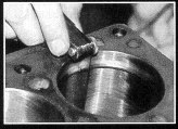
Feeler gauges were used to measure the piston ring end gap.
Blueprinting is the process of optimizing the tolerances within an engine. When a mass-production engine is designed, relatively wide tolerances are used to avoid expensive, high-precision machining. As a result, many of the clearances within a production engine fall outside of the range that will produce the best performance. It therefore follows that optimizing each of the clearances will improve both power and reliability. Blueprinting is permitted by most stock class racing rules, and since it’s the only method to legally increase power, it has become virtually mandatory for front-competitors.
Playing by the Rules
This article contains many tips from Dave Bean, who is one of the country’s foremost experts on Lotus Twin Cam engines. Dave has built a countless number of Twin Cams, with power outputs ranging from stock to unreal. Since many of these tips were too good not to mention, they were included; however, before building an engine for your chosen category of competition, check the rulebook to insure these tweaks are allowed.
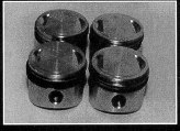
Hepolite +.040" oversized pistons increased both displacement and compression.
Crack Checking
While the bottom-end of a Twin Cam is quite strong, virtually all Twin Cam engines have been hammered on since they were new. Therefore, the first step in our engine building program was to have the critical components crack-checked. The crank and rods were inspected by Magnafluxing; fortunately, no defects were noted. If the flywheel and pistons had been reused, these also would have been checked; however, we chose to fit new oversized pistons and a Tilton aluminum flywheel to our project engine. Note that since Magnafluxing works only with iron and steel components. Aluminum parts are typically inspected with a dye penetrant; this technique would be required for the pistons and an aluminum flywheel.
Block and Pistons
A high-mileage engine block that has received no previous machining provides the best foundation for a blueprinted engine. When building racing engines, many professional engine builders prefer used engine blocks to new blocks. Blocks that have been in service for a few years have been heated and cooled innumerable times, and their castings have taken a final set. Once the block is fully re-machined, the newly machined surfaces will remain true, since no more shifting will occur in the casting.
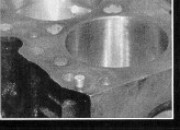
Oil passage restrictor plug is inserted in the block, and reduces the flow of excess oil to the head.
After removing the jackshaft bearings, the oil gallery plugs, and the freeze plugs, our block was cleaned in a hot tank. With all of the plugs removed, the hot tank cleaning fluid could effectively clean the internal oil and water passages.
Following the cleaning operation, the line bore of the main bearing saddles was measured. The line bore is the relationship between the geometric centers of the main bearing saddles. When viewed along the longitudinal axis of the crankshaft, the centers of each of the saddles must all be in line. If the centers are not exactly in line, the crankshaft will be forced to bend into shape when the main bearing caps are tightened. Even a minor misalignment of the line bore will cause uneven loading of the main bearings and cyclic bending loads in the crank. This situation will lead to accelerated bearing wear, reduced power, and possibly a broken crankshaft.
Main and rod bearings should be coated with Molybdenum Disulfide (MoS2) engine assembly lube.
The cure for this problem is fairly straightforward: a few thousandths of an inch of material is removed from the mating faces of each of the main bearing caps, the caps are bolted into place, and all of the saddles are rebored in line. Alternatively, the saddles can simply be rebored to a 0.015-inch larger diameter, and suitably oversized bearings can be fitted. Fortunately, our engine didn’t require line boring.
The top deck of the block was checked with a machined straightedge to ensure that it was flat and would provide no head gasket sealing problems. Again, our engine checked out just fine.
The final machine work on the block consisted of reboring the cylinders to fit 0.040-inch larger pistons. SCCA Solo 11 Stock and Street Prepared rules allow this overbore, as long as the piston crown remains the original shape (i.e., no domed pistons). On the Twin Cam, a +0.040inch overbore gives a slight increase in displacement (36 cc), an increase in compression ratio of slightly less than one-quarter of a point, and restores the cylinder bore to perfectly round.
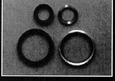
It all adds up: Special hard-lipped crank seals (right) have less drag than stock units and consume less power.
When reboring, the correct piston-to-wall clearance is determined by the construction of the piston to be used. Pistons are available in a few flavors, but the main ingredients that affect wall clearance are the skirt design and whether the pistons are of forged or cast construction. On a “tee” skirt piston, the piston crown is connected to the skirt only directly above the wrist pins; on a solid skirt piston, the crown is connected to the skirt over its entire circumference. A “tee” skirt piston tends to retain the combustion heat in the crown, since the heat transfer path to the skirt is limited. Having a much greater heat transfer path, a solid skirt piston dissipates considerably more heat to the skirt. With more heat being transferred to the skirt, the skirt will expand to a greater extent. Since piston-to-wall clearance is measured at the skirt, the piston-to-wall clearance must be greater when using solid-skirt pistons than when using “tee” skirt pistons. Piston-to-wall clearance must be further increased if the pistons are forged, as forged pistons tend to expand to a greater extent than do cast pistons.
For our project Twin Cam engine, we installed Hepolite cast pistons, and used a piston-to-wall clearance of 0.003 inches. To avoid interference between the oversize pistons and the head gasket, the outermost edges of the piston crowns were slightly chamfered. To measure piston ring end gap, each ring was placed in its appropriate cylinder, and squared within the bore by pressing it into the cylinder using an upside-down piston. The acceptable end gap for a Twin Cam is 0.012 to 0.018 inches.
Crankshaft
The key to making a high-revving engine live is to establish the proper main and rod bearing clearances. If the engine is to be consistently run at high revs, the bearing clearances should generally be increased. The increased clearance allows for a greater oil flow to the bearings. These clearances are set either by grinding the crank journals to the proper size, or by using special undersized bearings that provide additional clearance. We chose to use the standard bearings and turn the journals to the proper size.
Checking the machinist’s work. Plastigage was used to verify that the proper main and rod bearing clearances were achieved.
We used a clearance of 0.0025 inches for the rod bearings, and 0.0020 for the main bearings. The main bearing clearance can be slightly tighter than the rod bearings, since the main bearing loads are less severe and more uniform. Since we knew the clearance we wanted, we chose to allow the machine shop to turn the journals as necessary, rather than specifying a journal diameter. We gave the machinist the main and rod bearings that we would be using, which allowed them to determine the proper journal diameters by measuring the inside diameter of the mounted bearings.
Connecting Rods
The late-model Lotus 125E connecting rods are strong units, and work well with even heavily modified Twin Cams. The earlier 116E connecting rods aren’t up to the loads the engine will experience at high revs, and they should be replaced with the 125E units (be careful not to violate any preparation rules).
The connecting rods were first checked for straightness, and then the inside diameter of the big ends was recut to restore them to perfectly round. The recutting was accomplished in the same manner as would be done on a line boring job; a few thousandths of an inch was ground off the rod cap mating surfaces, the cap was bolted to the rod, and the big end was rebored.

Measuring crankshaft end-float with a dial indicator
The small end bushings were replaced with new bushings honed to a clearance of 0.0005 inches. Replacing the bushings allowed the effective length (i.e., the distance from the center of the big end to the center of the small end) of each connecting rod to be set identically. With each connecting rod having the same effective length, the piston heights were equalized, and therefore the combustion chamber volumes were more equal. Equalizing the combustion chamber volume results in a smoother running engine. Further, the top surface of the block can be milled to match the piston height, allowing the compression to be optimized for a given piston dome shape.

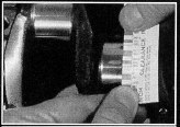
Dave Bean’s swinging oil pickup is free to rotate 360o, and follows the oil around the bottom of the oil pan.
Since connecting rod bolts are typically the most highly stressed fasteners in an engine, it’s wise to install new bolts as a part of every engine rebuild. The standard rod bolts are generally adequate for most applications, but for peace of mind we installed a set of Dave Bean’s 12-point rod bolts. These bolts have a much higher tensile strength than the standard units, and while perhaps unnecessary for an autocross engine, they were cheap insurance.
Balancing
The next step in our engine rebuild was to have the moving parts balanced. Imbalances in an engine create internal stresses which can destroy the engine at high revs. In addition, the vibrations caused by the imbalance result in wasted power; all of that shaking is caused by power being fed into the engine assembly, rather than out through the driveline. Every manufacturer balances its engines to some extent, but very few mass-produced engines cannot be improved by a careful rebalancing.
Two balancing techniques are currently employed. The “Detroit” balancing technique balances the engine as an assembly, while the “zero” balancing technique balances each part individually. While a perfect balance is more readily achieved using the Detroit technique, the zero balance technique allows individual parts to be replaced without a complete engine rebalance. We chose the zero technique to allow flexibility in future engine work. The components balanced for our project engine were the crankshaft, pistons, connecting rods, front crank pulley, and the flywheel and clutch assembly.
Oiling System
As previously mentioned, the Twin Cam has an oil starvation problem during sustained hard cornering to the right; the oil sloshes away from the oil pump pickup. If nothing is done to stop this, the results are inevitable: the connecting rods will provide an unwanted form of positive crankcase ventilation! Fortunately, several cures for this malady are available.
The best solution to oil starvation in any engine is a dry sump system. Since the dry sump draws oil from a continuously-filled remote oil tank, the oil pump always has a ready supply of oil. Further, a dry sump system can gain one or two horsepower, since windage is reduced in the oil pan. However, a dry sump system is also the most expensive solution to the problem (approximately $600). If you decide to install a dry sump, Dave Bean has all the pieces you’ll need.
An alternative method of dealing with the starvation problem is to install an Accusump. The Accusump is a hydraulic accumulator which stores a reserve supply of oil that is discharged when the engine oil pressure drops; when the oil pump resumes pumping, the Accusump is recharged. The volume of oil stored in the Accusump is dependent upon the normal operating oil pressure of the engine; for the Twin Cam with a standard oil pump, the volume is slightly over two quarts, while a high-pressure oil pump increases the stored volume to approximately three quarts. We have not tried an Accusump on our Twin Cam, but have had good luck with it on road racing Triumph engines; if we were to use one, we would also install a high-pressure oil pump to increase its stored oil capacity.
Oil pan baffles can be made, which successfully stop oil starvation; however, developing an effective baffle is often a trial- process, and we chose not to follow this route.
We solved the oil starvation problem in our Europa by installing one of Dave Bean’s trick swinging oil pump pickups. This clever little device has a pickup that is free to swing around the oil pan, chasing the oil as it sloshes. With the swinging pickup always immersed in oil, the starvation problem is eliminated. There’s only one problem with the swinging pickup-Bean doesn’t have any left in stock. He does have plans to produce a few more, however, and hopefully will have a fresh batch of them completed by the time you read this. Give him a call.
We also installed a high-pressure oil pump on our project engine to help the lubrication at high revs and high oil temperatures. This pump raised the normal operating oil pressure from 45 to approximately 65 psi.
Bean also recommends an additional modification to improve the performance of the oiling system. A restrictive plug with a 0.090-inch-diameter hole can be installed in the block to reduce the flow of oil to the head. In a Twin Cam, the valve train receives a disproportionate flow of oil when the engine runs at high revs, causing a build-up of oil in the head. Reducing the oil flow to the head allows more oil to be retained in the sump, and also provides additional flow to the crank and rods.
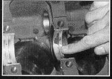
Water Pump
The water pump should be rebuilt, whether it appears to be in good shape or not. The water pump is built into the front timing chain cover, which is wedged between the head and the oil pan. If a pump failure occurs after the engine is installed, replacement is a murderous process due to all of the parts which must be removed and properly realigned.
Engine Assembly
We used Vandervell VP-2 bearings for both the rods and mains. This particular bearing type is used in the Cosworth DFX racing engines; obviously, it’s okay for our autocross Twin Cam. Prior to assembly, we coated each of the bearings and journals with molybdenum disulfide (MoS2) “moly” lubricant. Forget about all of the other assembly lube concoctions-moly is simply the best. It provides proper lubrication during the critical initial start-up of the engine, when no oil is in the galleries. Moly is available at any automotive speed shop. All gaskets were sealed using Permatex Hylomar sealant. This compound can be used on virtually all gaskets, including the head and exhaust manifold gaskets. Hylomar remains resilient after it sets and, unlike silicon sealer, it doesn’t ball up and clog oil passages. The crank end float was measured using a dial indicator. The correct end float for the Twin Cam engine is 0.005 to 0.010 inches; if the end float is found to be excessive, thicker thrust washers are available to bring it to within specs. The rod-to-crank side clearance was measured using feeler gauges; the correct clearance is 0.005 to 0.010 inches. The torque settings specified by Lotus are adequate for all of the fasteners used in the engine. These settings should be used to avoid over- stressing threads and/or distorting components. With the bottom end of the engine complete, it was time to move on to the head-a subject we’ll cover in the next article.
Further Reading
If you own a Lotus of any description, the most valuable reading available on the subject is Dave Bean’s Lotus parts catalog. This half-inch-thick book is much more than simply a listing of parts-it contains extremely valuable assembly recommendations for every subsystem on a Lotus. It’s also quite fun to read, being filled with clever tricks learned by Dave during his 15+ years of experience with Loti. The catalog is available for $6 (the best money you’ll ever spend on your Lotus) from Dave Bean Engineering
It All Adds Up
Virtually no modifications are allowed on a Street Prepared cylinder head, so it’s essential for the engine builder to pay close attention to all areas of head preparation. This attention to detail is the key to realizing a significant gain in horsepower from your engine rebuild. Since this is the case, it’s always best to have the work performed by a shop that has extensive experience in reworking your particular brand of cylinder head. Therefore, we chose Lotus specialist Dave Bean Engineering of Santa Barbara, California, to do all of our head work.
Head Hunting
Over the years, Twin Cam heads were produced in a variety of configurations. The engine designers juggled four primary design areas to create these configurations: compression ratio, valve size, cam specification, and carburetor type. The most desirable head used in an American-market Europa was the 115 HP Big Valve, which was fitted to 1973 and 1974 models; since Street Prepared rules allow updating or backdating of engines, owners of the earlier 105 HP nit will benefit from the installation of the more powerful Big Valve engine. This is the unit we used for our project car.
Have Your Head Examined
All cylinder heads are not created equal. Many of the late-model TC heads were produced with the ports slightly out of alignment, causing a reduction in the flow through the ports. This misalignment would be eliminated if the head was to receive a full porting job for racing, but Street Prepared rules prevent such hacking. It therefore becomes advantageous to have several cylinder heads to examine and choose from. Admittedly, very few competitors have more than a single head on hand; however, shops specializing in Lotus will often have many available, and trades are often possible.
When examining a head, it’s important to inspect for previous machine work; the head may have been modified beyond the legal limitations. The ports and combustion chambers must be original, and the head should not have been milled. The face of the head should be checked with a machined straight-edge to ensure that it’s perfectly flat. The condition of the seats is unimportant, as these will be replaced; however, the seat area of the combustion chamber should be closely checked for cracks.
If you’re not going to be running your Twin Cam in either the Stock or Street Prepared categories, you may not care that the head needs to be or has been milled; you may want the associated increase in compression. However, if the head shows signs of warpage or has been milled for reasons unknown, it is extremely important to check the line bore of the camshaft bearing saddles. When a head warps, it will be distorted on the top side as well-the side that supports the camshafts. This top-side warpage will cause the camshaft saddles to become misaligned, and the cams will bind in the bearings. This binding will cause at the very least a loss of power and accelerated bearing wear; at the worst, it will cause broken camshafts and chunks of stuff ricocheting inside the engine. If the line bore is found to be distorted, all is not lost; the cam bearing saddles can be linebored to restore the proper geometry (an expensive proposition, typically costing around $250).
Do not glass bead your aluminum head to clean it. While glass beading makes a beautiful finish and is an effective method of removing carbon from the combustion chambers, a portion of the glass beads will become imbedded in the aluminum. It will then be virtually impossible to remove the beads from the metal prior to assembling the engine. Once the engine becomes operational, the vibrations of the engine will dislodge the glass beads, allowing them to merrily circulate through the internal workings of the engine. The Street Prepared rules allow for the ports to be machined up to one inch in from the mounting faces of the intake and exhaust manifolds, allowing the manifolds and ports to be matched. On the Stromberg head, this rule allows for a significant improvement in the flow through the intake tracts. That’s because the port walls feature a stepping which requires the intake charge to abruptly change its direction of flow-and fortunately, the step is within the first one inch of each of the intake tracts. This step can be legally removed by grinding and shaping the port walls so they blend in smoothly from the intake manifold.
The Valve Grinding Operation
The primary reason for reworking a cylinder head is, of course, establishing a proper seal between the valves and their seats. However, the manner in which the valve job is performed will have a significant impact on the power output of the engine.
When a valve job is performed without installing new seats, the seats will by necessity require grinding to establish the proper finish. This grinding causes the valves to become slightly recessed into the intake or exhaust ports, resulting in a loss of power. This power loss is caused primarily by the valve and seat geometry restricting flow of the intake and exhaust gases at low valve lift, and by an increase in the combustion chamber volume, which reduces the compression ratio. Therefore, if the seats require more than a light touch-up, they should be replaced to maximize the engine’s power.
When performing the grinding operation, it’s desirable to have a small contact area width between the valves and the seats, since a small contact width will improve flow at low valve lift. However, the valves rely on this seat contact for heat dissipation, and an insufficient contact area will cause the valve faces to overheat and burn. Dave Bean recommends a contact area width of 0.040 inches for the intake valves and 0.060 inches for the hotter-running exhaust valves (on a racing engine, Dave squeezes these down to 0.030 and 0.040 inches, respectively). To set the contact area width, the seat is cut immediately up-port from the contact area (the port diameter is enlarged directly underneath the valve head) until the contact width is reduced to the desired value. The location of the contact area on the valve face is also important. The distance from the contact area to the outer edge of the valve face is referred to as the margin. If the margin is excessive, flow past the valve will be reduced. If the margin is too small, the valve will be more susceptible to burning. Bean uses a margin of 0.040 inches on both the intake and exhaust valves.
When the valve seats are ground, the faces of the seats are cut at a 45° angle. To further improve the flow past the valves, additional grinding can be performed on the seats immediately up-port from the area of contact between the valves and seats; this is the process used to create the so-called multi-angle valve job. By grinding an additional two angles into the seat, with each successive angle being more parallel to the port than the previous, the profile of the seat is rounded in the area near the valve, and flow past the seat is thus promoted.
To maintain the thin line of contact between the valves and the seats, it is essential not to overdo the valve lapping operation. The purpose of lapping is to provide the optimum finish and fit between the valves and the seats, and only a minimal amount of lapping is required. When the areas of contact on the two components have a uniform gray appearance, the lapping process has been completed.
The Valve Sprints
Valve springs do “wear out”. After years of being preloaded in service, the free length of springs tends to decrease. This decrease in the free length of the springs will cause a reduction in the spring preload on the valves. If the spring preload drops to around 45 pounds, the valves will tend to bounce on the seats at high revs. Since the actual rate of the spring will be unchanged, the preload could be restored by shimming under the springs. The springs on the Twin Cam head, however, have little room for shimming before the coils will bind at maximum lift (particularly if a high-lift cam is installed). If this is found to be the case (and it should always be checked), it will be necessary to replace the springs with new units. It’s a good idea to replace the springs anyway, to eliminate the possibility of old springs breaking from fatigue.
Dave Bean recommends a spring preload of at least 55 pounds on a stock camshaft, with 65 pounds being preferred. With this preload, the stock springs are good to 7500 RPM when using the stock cam profile. For high-lift racing cams, Bean increases the preload to between 75 and 85 pounds. Preloads much higher than this will cause accelerated cam lobe wear, higher stresses on the valve train, and possible coil binding. While lightweight valve train components are neither needed nor allowed on a Street Prepared engine, they reduce the spring rate requirements demanded in a highly-modified racing engine. High-lift cams and an increased engine speed require the valve assemblies to accelerate and decelerate at much higher rates than when using the stock hardware. Lightweight valve assemblies allow the valves to closely follow the profile dictated by the camshaft, without requiring the valve train to have excessive valve spring loads.
The Valve Tappets
The previous owner of our Europa apparently believed that changing the oil was a pointless exercise. Upon teardown, our engine showed the results of this man’s theory: worn parts everywhere. In addition to the lovely sight of gold main and rod bearings, the top end of the engine looked quite tired. Dirty oil wreaks havoc on the cam tappets and the tappet sleeves, causing the tappets to rattle around within the sleeves. The upper limit on the tappet-to-sleeve clearance is 0. 003 inches. Since we wanted to do the engine right, we replaced both the tappets and the tappet sleeves.
The Valve Guides
The valve guides should be replaced as part of every valve job. The Twin Cam engine was designed with the lightest valve train possible, which means short valves and therefore short valve guides. As guides wear, the valves are more susceptible to rocking during operation. This rocking causes an inconsistent seating of the valves and an attendant loss in power.
The best guides to use are those made of bronze alloys. In comparison with iron valve guides, bronze guides have a lower wear rate due to lower friction between the guide and valve stem, and they provide superior heat transfer. But the greatest advantage of bronze guides is the ability to run much tighter guide-to-stem clearances. This tighter clearance provides a more consistent seating of the valves, thereby providing an improvement in the sealing of the combustion chamber. When working with bronze guides, Bean hones them to size, running minimum clearances of slightly under 0.001 inches for the intakes and slightly over 0.001 inches for the hotter-running exhausts.
The Cam Bearings
Two widths of cam bearings are used on a TC head. As it turns out, the narrower bearing provides sufficient support to allow it to be used for each of the cam journals (with the exception of the frontmost bearing, which must have an oil feed hole). By installing the narrower bearing in each of the cam bearing saddles, rotational drag on the engine will be slightly reduced (remember, it all adds up!). If the bearings are bought as a rebuild set, you will receive the usual mix of narrow and wide bearings. However, Bean has the narrow bearings available individually, and he will gladly supply you with a sufficient number to complete the job.
The Carburetors
While the Big Valve was the most powerful engine fitted to a U.S.-spec Europa, it was equipped with the lowly Stromberg emission carburetors, rather than the much more desirable Weber or Dell’Orto carburetors available on the European versions. Without the emission controls, the European Big Valve produced a healthy 126 HP; obviously, the Stromberg carbs cost the engine a bunch of power.
Street Prepared rules allow the carburetors and intake manifolds of an engine to be changed; unfortunately, the two barrel Euro-carbs will not simply bolt onto a head that was originally equipped with Strombergs. Oddly enough, Lotus chose to cast a head with intake port runners that were designed specifically for single throat carburetors, rather than simply adapting the Strombergs to the original Weber-equipped head. And to make matters worse, a switch to a Weber head wouldn’t be legal in Street Prepared, since no Weber-equipped Europas were ever imported into the U.S. What all this means is that you’re pretty well stuck using two single-barrel carburetors for the induction, and the options are limited. Good results have been reported using 2 inch diameter S.U. carbs in place of the 1 3/4-inch Strombergs; however, we have had no experience with this set-up. We chose to stick with the Strombergs.
The rather poor throttle response of the original carb setup can be significantly improved by eliminating the intake crossover tube, which is used to heat the intake charge to reduce emissions. By removing the crossover tube and the secondary throttle butterflies, and capping all the holes produced by this operation, the intake charge from the carburetors is provided a much more direct shot into the combustion chamber.
The Exhaust System
Exhaust systems on Street Prepared cars may be replaced or modified at will, provided the noise is kept under control. Bean manufactures a “tri-Y” (4 into 2 into 1) tubular steel header, which is adapted to a low-restriction muffler. This header is sized to improve the powerband of lightly warmed-over engines, rather than being designed for the requirements of highrevving racing engines. This system also serves to cut a significant chunk of weight, saving several pounds over the stock system.
| Twin Cam Blueprinting Specifications | (courtesy of Dave Bean Engineering) | |
|---|---|---|
| Main bearing bore dimension (standard) | 2.2711 - 2.2716 inches | |
| Main journal diameter (standard) | 2.1251 - 2.1258 | |
| Rod journal diameter (standard) | 1,9367 - 1.9374 | |
| Crank end float | 0.005 - 0.010 | |
| Rod big end inside diameter | 2.0827 - 2.0832 | |
| Rod side clearance | 0.005 - 0.010 | |
| Piston-to-wall clearance | ||
| Cast piston, “tee” skirt | 0.0020 - 0.0030 | |
| Cast piston, solid skirt | 0.0030 - 0.0040 | |
| Forged piston, solid skirt | 0.0035 - 0.0040 | |
| Piston ring end gap | 0.012 - 0.018 | |
| Piston ring to groove clearance | ||
| New | 0.0015 - 0.0020 | |
| Wear limit | 0.0040 | |
| Wrist pin nominal diameter | 0.8120 | |
| Wrist pin to rod clearance | 0.0005 - 0.0009 | |
| Wrist pin to piston clearance | 0.0004 - 0.0008 |
Copyright by Grassroots Motorsports, Vol. 7 No. 3, May/June 1990
COPYRIGHT NOTICE: This article is reproduced for non-commercial historical preservation purposes only. Copyright remains with the original publisher. If you are the rights holder and have questions or concerns about this content, please visit our Copyright and Historical Preservation Policy and contact us. We will respond within 24 business hours and will remove or restrict the content promptly upon a valid request.