Fiting QED fuel injection

STARTING THE ENGINE:

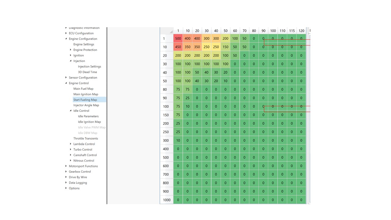
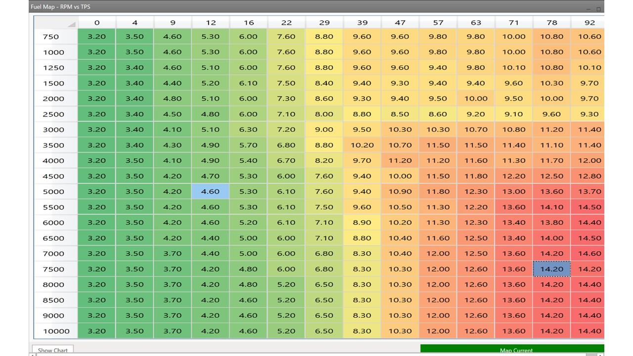
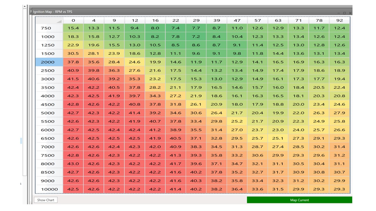
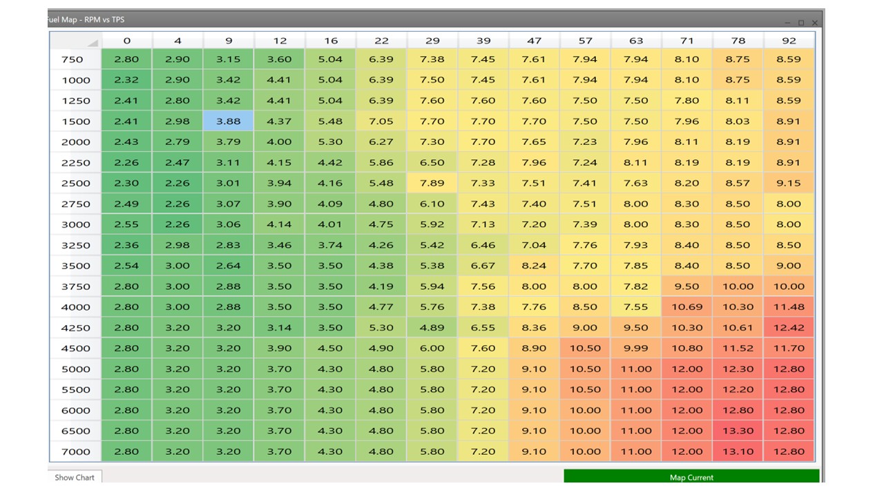
Once the sensors are all working, injectors and coils all firing, engine timing synchronized with the ECU, and Fuel pump is delivering fuel at the relevant pressure to the injector it is time to try starting the engine. This first start may be tricky so be patient. On the maps the important cells for starting the engine will be the 0-4% throttle opening at 750-1500 rpm so only 6 cells need to be optimized to begin. The timing can be set to the initial timing advance for a twincam (remember the number is the total advance which in a traditional distributor would be static + any dynamic timing). Later you will generate a 3D timing chart (probably best done on a rolling road).

The fueling table in this area is a bit of a guess to begin.. I began with putting “8” in the cells on the top left (I amusing the pico injectors from QED). This is very rich but helped the initial start. I also sprayed some ether into the inlet to help things along. Pressing the starter got the engine firing and after a few firings then dying the engined fired up and I reduced the fueling to closer to 4 (to do this enter 4 in the greyed out cell, the grey cell is closest to where the engine is running) and press F4. I modified this number until the engine ran smoothly and then let it run up to temperature. As the engine warmed I reduced the fuel (like pushing in the choke).

Now I was lucky the engine fired pretty easily. There are other scenarios .

1) If the engine does not fire at all even with ether then check your spark and fuel and if there is spark check the synchronization (you can see whether synchronization is working by looking at the Diagnostics Display in Diagnostics Information Menu) and the Sensor Position figure in Engine Settings under the Engine Configuration men u.

2) If it backfires, check the synchronisation and the Sensor position figure in Engine Settings under the Engine Configuration me nu.

3) If the engine fires and dies, check the idle setting on the Throttle bodies a little and/or add a little more f uel.

4) If the engine fires and the idle is too high (you may need to switch of quickly if this happens) close the idle setting on the throttle bodies.

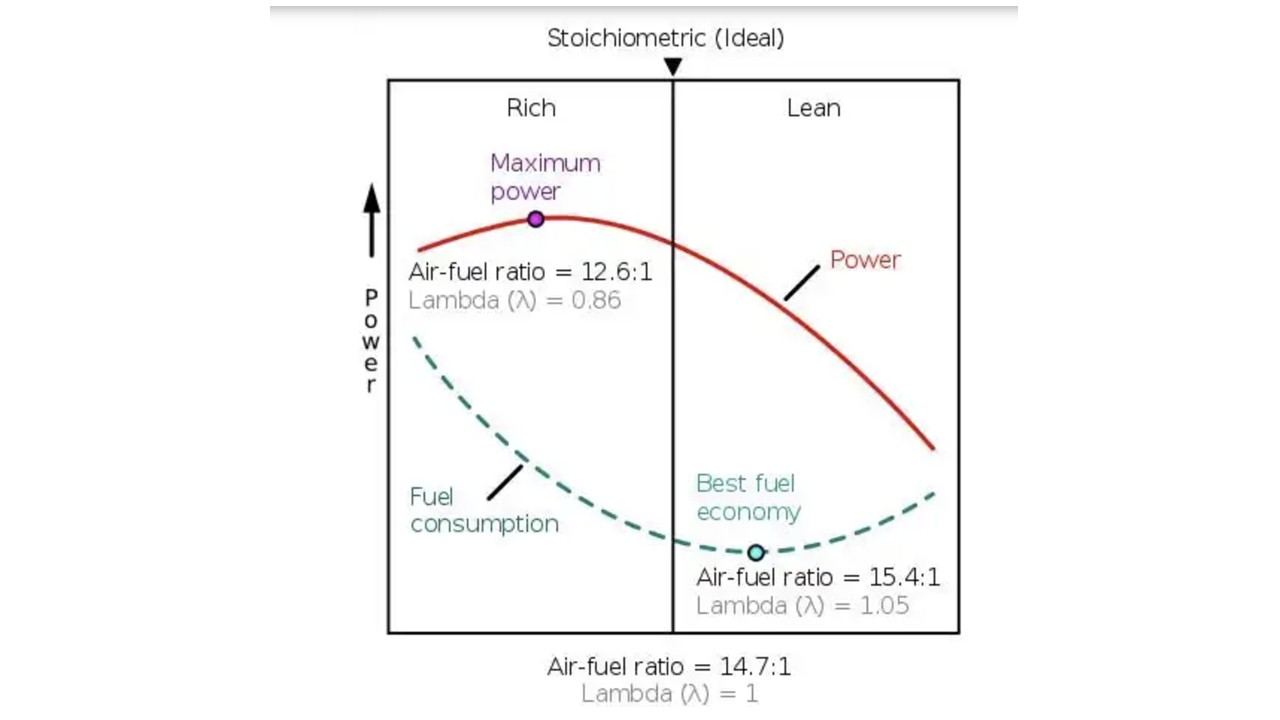
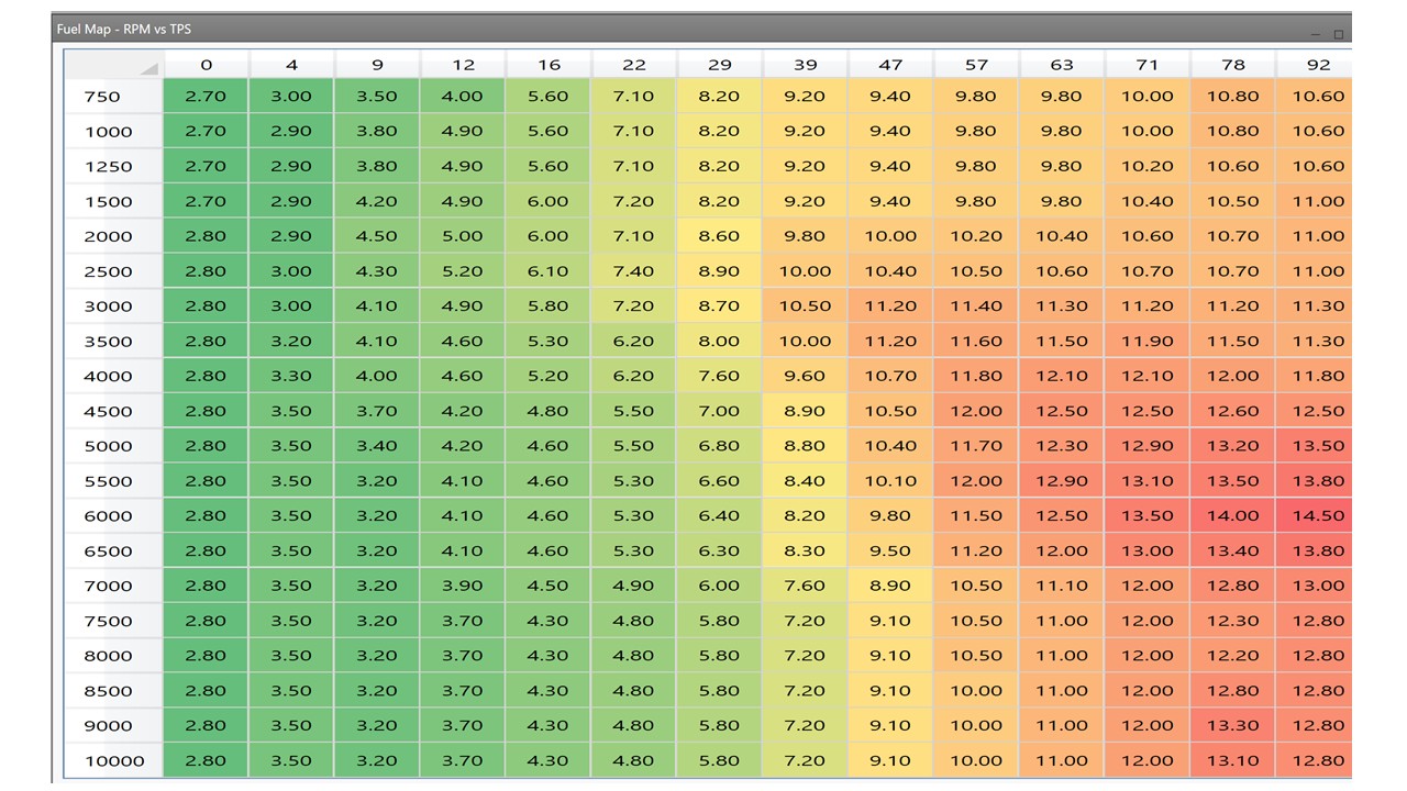
Once the engine is up to temperature and idling at a reasonable value you can check the AFR (see AFR meter in Live Data or the AFR meter on the Dashboard). Ideally you want this between 13-14:1 AFR or 0.9-1 Lambda. You can achieve this by altering the grey cell on the fueling map. Reducing the value weakens the mixture increases the AFR and Lambda. Make modest changes (say 0.2) and then press F4 to send the new value to the ECU. If you go too far the engine may falter or stop so just go back to the original value. Once you have a steady mixture in the required are you may also have changed the idle RPM which you will notice has changed where the grey cell is located. For now alter the idle adjustment on the throttle bodies to compensate (later on you can use the ignition based closed-loop system to control idle speed).

Now that the engine is idling you can try blipping the throttle gently to see if it responds. The initial Q360 map from QED seemed to work ok here and my engine revved freely. Now you have the engine up and running give it a good check for leaks etc. and check the fan goes on if you have connected it to the ECU. At this stage I stopped the engine and went for a celebratory cuppa!

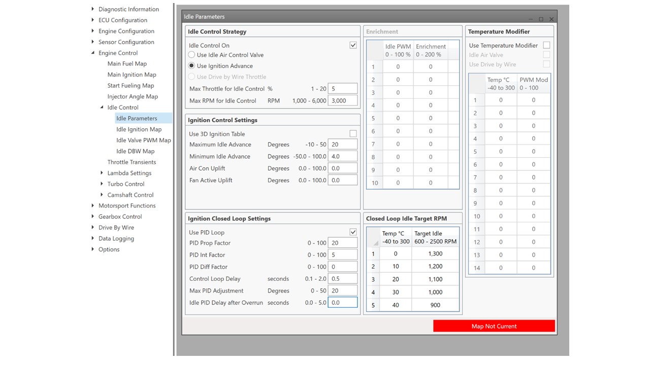
NB: restarting from cold now may still need you to manually add some fuel to the map and remove it (manual choke :blush:) or add some ether to the inlet but you should now be able to start the car at will and it should progress to idle. It is quite possible that the idle you set when the engine is warm, using the idle screw on the throttle bodies, might be too low an idle as the car is warming. To resolve this you will need to set up closed loop, ignition based idle control.

2 Likes

Well done great write up

SETTING THE STARTING MIXTURE CONTROL.

Now you have a stably idling car with correct mixture at idle you will be itching to do some mapping (either on the road or at as rolling road). For me this was on the road (more of that later), which meant that I would have to do several sessions and hence I would need to start the car from cold each time. Initially I did this by artificially enrichening the fueling on the 4 cells at the top left of the fueling table, starting the car, and then reducing them slowly to the level set with the engine warm.. Kinda like using a manual choke. However, obviously this is not what you want to do every time you start the car. So I took the opportunity of repeatedly starting the car from cold to set up the cold start parameters on the EFI (This is a good use of this stage in tuning as you can only set up the cold start parameters when the engine is cold:blush:).

The T2 has a couple of features which allow you to manage cold start, but first why is cold start an issue. There is a lot on the web about this, but basically to begin with the inlet manifold cold fuel tends to condense on the its walls meaning there is less fuel in the mixture and hence it is lean. This means you need to add more fuel at start up to ensure you have enough fuel to start the car. Eventually the walls of the inlet manifold become saturated with fuel and as the manifold warms condensation becomes less of a problem so that no additional fuel is required. This means that startup fueling involves initially enrichening the mixture followed by slowly reducing this extra fuel. To do this the T2 offers 3 sets of parameters to alter :

1) You can add a single slug of fuel on startup in addition to the usual injection pulse. This is to wet the manifold surfaces and to clear any air in the injectors. This is set in the Injector Settings window in the Injection part of the Engine Config menu. It can be set between 0-80 milliseconds. I set mine at 40 ms to begin for no reason but that it was half way. It is something that I might fiddle with later.

2) You can set up a Starting Fuel Map (found in the Engine Control Menu), which adds more fuel over a set number of engine rotations from first startup. This can also be scaled based on the water temperature. More of that below.

3) You can also setup standalone enrichment based on the water temperat ure.

You might wonder why you have both options 2 and 3? Surely option 2 should suffice, but 2 is only operative for a set number of revolutions of the engine from start while 3 is purely based on water temperature. You might also say why not just have option 3 and fuel entirely by water temperature. The trouble with this is that the engine needs a lot more fuel for the first few revolutions after a start. So really you need both and unfortunately both sets of parameters interact during map ping.

My approach was to set up the start fueling first working on Option 2 and then move on to sorting option 3 later. The Start Fueling Map that I eventually ended up with is below (it seems to work well as the engine starts from pretty much first turn):

As you can see the map consists of 2 axes, one for water temperature and the other for engine revolutions. In each cell is a number which corresponds to a percentage increase in fuel. So the number 100 means 100% more fuel above the current fueling in the fueling map. So if it is 3 ms of fuel in the map at idle a figure of 100 will mean at start it will be 6 ms of fuel. As you can see in the map the first 0-20 revolutions of the engine gets a very large increase in fuel (wetting the inlet manifold) before it very quickly tails off to no enrichment. This is very much like certain forms of manual choke where you pull it out fully to start and then press in half way for warm up. It is also like the weber carbs on an elan where you press the accelerator a few times before the start to dump some fuel into the inlet tract. What you can also see is the amount of enrichment required diminishes with increasing temperature which makes sense as there is less condensation on the manifold at higher temperatures. It is also worth noting that that realistically you won’t be starting your car “from cold” with the engine at temperatures above 40 degrees unless you live somewhere VV warm:blush:.

To tune this map you need to, of course, repeatedly start the car from cold so it takes some time and some trial and error. Things to look out for. If you over fuel you will end up with fouled plugs and you can kinda hear it as the engine “fluffing” as it floods (you may also seen some black smoke out the tail pipe and a smell of unburnt fuel). You can often

also hear the engine note “clear” as the fueling drops off after a number of engine rotations. If that happens you know to lean out some of the earlier fueling. If the fueling is too weak after the initial start the engine idle will generally drop and then die. Next time you start add a little more fuel. Helpfully if you watch the starting map when you start the car you can see a greyed out cell which is where the car is in terms of rotations and temperatures. So you can actually see which cells might need changing next time. In my case I landed on a good initial enrichment pretty quickly and then just had to keep the enrichment going longer than my initial guess (adding more fuel in the 100-150 rotations cell). Luckily for me I also did this process during the winter in the UK so the engine temperature was generally between 0-10 degrees. If you do this during the summer you might need to do some tweaks to the map when the weather gets colder.

The next thing you need to do is to sort the water temperature enrichment (option 3). For this I got the car up to operating temperature and made sure that the idle AFR was where I wanted it to be. I then restarted the car the next morning from cold. Once the car was off the start fueling map (after 300 rotations) I looked at the AFR value. It was too lean (not unexpected) so I added more fuel to the relevant temperature cell in the Sensor Compensations (Fuel Comp %) in the Water Temperature window until the AFR moved into the correct window (AFR 13-14:1). As the water temperature rose to the next cell (e.g.10 degrees to 20 degrees) as the engine warmed I rechecked the AFR and adjusted the fueling compensation again until the car reached operating temperature. It took a couple of iterations but I quickly managed to get something where the AFR was pretty stable from start. One thing to note here though.. As the compensation and start fueling figures are percentages of the figure in the main fuel map, if you have to alter the main fuel map it will alter the effect of any compensations so you may need to tweak them again.

1 Like

So grateful for sharing this info! Thank you

Thanks. More to come this weekend!

SETTING UP CLOSED LOOP IGNITION CONTROL OF IDLE SPEED

The T2 has 2 of ways of controlling idle speed. You can use an idle air control valve (IACV) which is an electrically controlled valve which enables more air to be added between the throttle bodies and the engine. This is like opening the throttle butterflies a little. For a twincam with individual inlet tracts you would need to drill and tap each of the 3 inlet tracts and add a tube through which air can be added. I wasn’t willing to do this so I opted for the second control method. This uses changes in ignition timing to alter idle speed. Moving the ignition timing from the optimum has the effect of reducing idle speed, moving it closer to optimum can increase the idle. The ECU uses this method monitoring the RPM in order to optimize the idle at all engine conditions. The details of the idle control system are shown in Idle Parameters in Engine Control .

![|602x443](file:///C:/Users/trdaf/AppData/Local/Temp/msohtmlclip1/01/clip_image002.png)The figures shown in the window are initial settings you will need to sort your won settings. I have selected Idle Control “on” and “use ignition advance”. The Max and Min idle advance are the maximum and minimum that the system can move the advance during idle speed optimization. Suggested figures to begin with are in the manual. You can also add an uplift in idle if you are running the cooling fan from the ECU. Cooling fans use a reasonable number of amps causing the alternator to slow the idle, this setting solves this. It is also suggested in the manual that you use PID closed loop which is selected. This allows you to set different target idle speeds at different engine temperatures. Generally a slightly high idle speed when the engine is cold helps with running. Much like the part way in position on a manual choke. The Closed loop system is controlled by a PID (Proportional, Integral, Differential) control system. Which has 3 important parameters P, I And D. What numbers these should be set to seems to be a bit of a trial an error process. The suggestion being to start with P and increase the number, this increases the strength of the drive towards the target. At some point you end up in a situation where the effect overshoots and this leads to oscillations. You should then back off the figure until you get some stability. You can also increase D to reduce the tendency to overshoot and also to remove any steady state errors. Generally you may not need to alter D. Play with there figures until you have the desired behavour. You can test this by tapping the accelerator and see if the idle drops back to the chosen rpm in a time you find acceptable.

It should be noted that it is also possible that you could have manually set the idle too high or too low (using the adjustment on the throttle bodies) for the PID controller to handle.. e.g. if it is manually set too high the PID may not be able to alter the advance enough to compensate. If this is the case, adjust the idle manually and the PID should settle it to the desired RPM.

1 Like

SORTING THE FUELING AND IGNITION MAP

Now you have an engine which idles steadily with a good AFR it is time to begin to tune the overall fueling and ignition map. As partly explained earlier, these take the form of a table of numbers representing fueling levels in milliseconds of time the injector is open at different engine speeds and throttle open percentages. On the map I have setup this includes 14 different throttle opening levels and 20 different engine speeds leaving me to sort out the fueling in 280 different conditions. This is a LOT. I should say at this stage one way to sort these is to take your car to a rolling road where they will set them up for you. This is a very good idea if you do not feel confident with sorting the fueling map.. In my case I thought I would see how close I could get by driving on the road and assessing the Logging data that the ECU produces (more of that later). But first, although there are 280 fueling values to sort, actually there are many less that you actually use during standard motoring. So the task is actually simpler than it seems. Lets look at a Map…

Below is a map supplied by QED for the Twincam. Interestingly this map was actually formatted for a previous version of the DTAfast ECU and took some work to reformat for the T2. (As we will see it is also not a very good map, at least for my pretty bog standard big valve). Now it is worth thinking about what the values in the cells mean. They are the amount of fuel being injected into the airstream after the throttle plates. To have an efficient burn of the fuel you need a 14.7:1 ratio between the amount of oxygen in the air and the amount of fuel. This is the best value for efficiency whereas a little more rich (closer to 12.6:1) is better for power .

When you are running the engine apart from the speed the main thing that changes is the amount of air (which of course includes oxygen) that the engine can breathe in. This is controlled by a couple of factors but the most important one is the throttle. At idle for example the throttle is almost completely closed this means the engine can only breathe in a small amount of air and so needs less fuel. Compare this to fully open throttle, where the engine is able to pull in the maximum amount of air and so needs more fuel. This means that the map should have lower fueling numbers at low throttle opening and higher fueling numbers at higher throttle openings.. Makes sense right.. But then you might say… So all we just need to alter the fueling vs throttle opening and all should be fine.. That would make things really simple, you only need 14 different values. Unfortunately this is not correct. The amount of air the engine can breathe is also effected by how fast the engine is running. An analogy: Think about the difference between taking deep breaths very slowly and then trying the same as fast as you can (don’t hyperventilate!). When you breathe slowly there seems to be minimal resistance to breathing in air. However when you breathe fast the air seems to resist.. This is an indicator of differences in fluid (air in this case) under different flow velocities. The same is true for engines.. flow at high rpm will be different to flow at low rpm effecting how much air the engine breathes in and hence altering the amount of fuel you need to put in.. Similar things happen with different cam profiles and overlaps and different exhaust manifolds which induce pressure waves which can literally suck exhaust gas out of the engine increasing the amount of air they can breathe in.. So you see it is complex.. and you need to adjust fueling for both throttle opening and engine speed. But the main concept to remember is that the amount of fuel you are injecting under any condition should reflect the amount of air the engine breathing into its cylinders.

Now let’s look at the map. First thing to notice is that the throttle position axis is not uniformly spread, with more cells below 25% than above it. This is because the amount of air being breathe by the engine changes the most when the throttle is just opening. This in turn means that the fueling requirements change the most and so having more fueling cells down in this region helps us to tune it more effectively. Second thing you will notice is that fueling does increase as the throttle opens which makes sense. You will also notice that the fueling requirements increase as RPM increases at large throttle openings. This indicates that the engine is able to breath more effectively at high RPMs due to the combination of the cam profiles and exhaust tuning.. This is what you want in a sporty engine as it is here that BHP is generated.

Looking more closely we can define areas based on the driving condition. Top Left (low RPM Low Throttle opening) is where your engine idles which is why we worked on that at the beginning. Bottom right (High RPM and High Throttle) is when the engine is running at its max. Bottom left (High Rpm, low throttle) corresponds to when you take your foot of the gas after reving the engine hard (e.g. during slowing down or gear changes). Top right (Low Rpm, high throttle) is when you punch the throttle a low rpm, this is actually an area were very little driving is done so less important. These 4 areas apart from where we idle are all actually areas which are rarely used unless you are a racer and hang the car at max revs a lot. Instead for a road car most driving is done close to cruise and acceleration up to cruise (I know we all like to give it some beans so won’t admit to this, but it is actually true). This region, which is between 0-60% throttle and 1000-4000 RPM is the area which you really need to focus on for a drivable car on normal road conditions. This reduces the number of cells we need to find fueling numbers by about 50%. This does not mean that the other cells should contain zeros of course but we can get reasonable estimates for them as we proceed.

1 Like

TIMING
Alongside the fueling map is a timing map, which like the fueling map has one axis of throttle opening % and one of RPM. The key aim with the ignition map is to have enough advance for maximum power but not so much that you get pre-ignition (aka Pinking or Pinging) which damages the engine. As it turns out the increase in power higher advance settings flattens (see graph) out which means if you don’t want to risk engine damage you can leave a good margin without loosing too much performance.

The map supplied from QED is below. You can see that in general (as expected) the amount of advance increases with RPM (at higher engine speeds you need to move ignition earlier in the compression phase to allow sufficient time for fuel to burn). What you also see is that advance flattens out at high RPM and that we have very high advance at high RPM low throttle which is where we may also have a lean mixture either on overrun or cruise to enhance MPG. Lean mixtures take longer to burn so must be ignited earlier. What looked a little odd to me is that in the working range (Throttle position 12-50%) the advance didn’t reach 30 degrees BTDC (towards the max suggested for a twincam) until quite high rpm (6000-7000RPM) which seemed wrong.. I would have expected this value to be reached >3000 rpm.

Even though the ignition map looked a little odd, the car started on this map (with the starting and idle settings mentioned earlier) and I took it for a spin to the petrol station.

This short run < 1 mile, highlighted 2 immediate issues with the map. Firstly above idle the car ran very rich with the ECU registering AFRs close to 10:1, secondly, the car felt sluggish. The AFR issue clear meant that the map was too rich. The sluggish-ness was either over fueling or timing (not advanced enough) or both. For an experiment I altered the whole of the map by decreasing all the fueling by 10%. You can do this by selecting all cells and pressing F5 which allows you to change values by an integer or %. I went for a second drive and the AFR leaned out a little to closer to 11:1 (still not good, but at least it is in the correct direction) but the car was still sluggish.

At this point the plugs fowled which is another sign that too much fuel is being supplied !

To me this meant I would have to do a lot of work on the whole map or go to a rolling road. So I decided to ask DTA (who supply the ECU) if they have a better map. They said the only map they had was the one supplied by QED but that they would send it anyway (V helpful people). I loaded up the map (see below) and was surprised to find it was quite different. For one it was in the correct format, secondly it looked a lot leaner and the timing looked better but still not quite what I would expect and thirdly it had settings included for a lot of other aspects including start fueling which were a lot better than the QED map (which had none). NB: The ones I showed above in the start fueling section are slightly modified values from the DTA map.

I started the car (which was a lot easier with the correct starting enrichment), altered the mixture at idle so that it was close to 14:1 and then went for a drive.. The difference was immediate. The AFR was pretty much 12-13:1 across all conditions and the car was nice and peppy. This is a much better starting map.

Now there are several routes that I could have taken from here to get a final map :

1) Go to a rolling road (the map was good enough to get me there). Expensive, and where’s the fun in letting someone else do thi s.

2) Drive around with someone watching the AFR at a number of steady state conditions (basically driving in different gears at sustained RPM on different gradients) and then altering mixtures in the cells corresponding to those driving conditions to get the correct AFR. Nice idea, but I don’t have any friends a) interested in learning how to do this and b) with time to sit with me doing this :grinning_face:

3) Try and do it on my own

I chose 3) because I have done this before with cars on carbs (SUs, Webers, Dellortos & Holleys) and Lucas mechanical fuel injection (Triumph TR6). Normally for me this involves driving while logging data from the car (you can log data on both the ECU and Laptop with a DTA ECU). Going home, and dragging the RPM, TPS and AFR data onto Excel, identifying areas where I was driving at a stable RPM (gives the a stable AFR) and then changing the fueling in the cell that corresponds to the RPM and TPS. This is doable but in the past it has taken quite a few weekends to get this to work. Feel free to do it, it works and is kinda fun as the car gets better and better….

In this case I decided to go all modern and high tech and harness the wonder of AI. Using ChatGPT to write a Python script to read in the current map and log files and few bits of statistics I built a program that does what I did in excel and many weekends in < 1 second. The output being an improved map. Chatgpt even generated a simple user interface that even showed the data, identified which bits of data were used in the analysis and a measure of how close the current map was to the chosen AFR (I am happy to supply the code with no guarantees). The DTA map, untouched was around 20% (RMSD) away from a chosen optimum of 14.7. Not terrible.. but not great… One round of optimisation using the programme and it was at 5% (you can see the map below). Now this is not a final perfect map because these approaches can only optimise the cells that you can drive at safely and stably on the road. For example, it is hard to maintain 6500 rpm stably on the road (unless you are driving in first gear), However, naturally, what you do collect data on (and hence optimise) are cells corresponding to conditions under which you normally drive.

Overall the car was pretty good now, it started first turn, restarted cleanly and drove well with no hesitation (due to transient enrichment, more of that later). However I was still not that happy with the ignition timing so I altered it based on timing DTA used for a similar twincam engine of a similar capacity (I can’t remember which). See below.

As you see the advance comes in earlier (You will also note that I altered the overall map as for some reason the one I had went to 10,000 RPM !). I repeated the mixture optimisation (not much change needed truthfully) and the car was awesome, better acceleration..

1 Like

Hi,
Very interesting to see a PID three term controller used in there for the idle contol. This algorithm has basically 3 forms, each type depending on the equation used to build it. Out of interest this is the most commonly used alogorithm in use today (world wide) in industrial process control systems. Several methods exist for tuning PID loops but pole/zero cancellation, aka “Lambda Tuning” is a reasonable method. Unfortunatley to get the best results a “model” of the process is required, typically a “bump test” would suffice. And lastly, this algorithm is best suited to 1st/2nd order systems.

The above from another life…

cheers
Mark

Hi Mark

Been their done that :slight_smile:

cheers
Rohan

Hi Rohan,
I must have tuned 1000’s of loops in my time, ranging from simple, complex to multivariable DMC controllers, thank god I’m retired now. But very interesting at the time, especially those with odd dynamics…

cheers
Mark

Yes my son who has just finished a mech engineering degree gave me a bit of tutorial. To me it looks like most people dont do much fiddling of the parameters. But my first view using the suggested presets it works ok if slightly slow sometimes. Perhaps 1-2 second to settle the idle to 1000 but no oscillations.

Tim