I have made some very minor progress. This is the fuel injector harness:
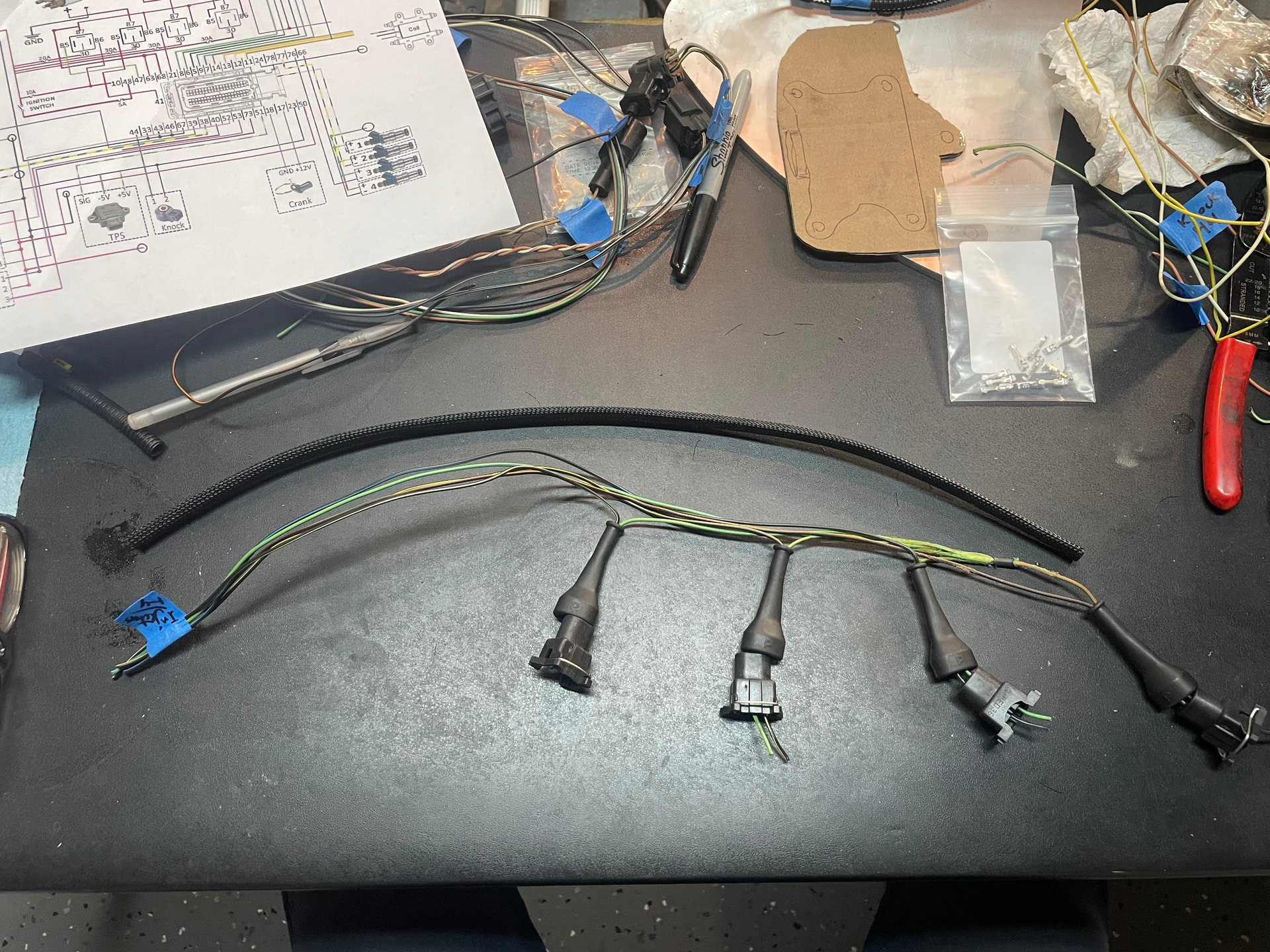
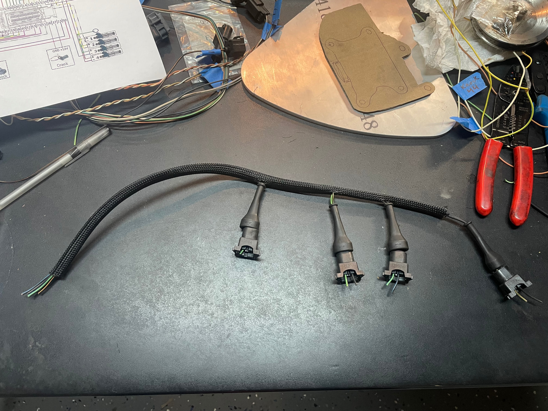
I will also be routing the Throttle Position Sensor, Intake Air Temp Sensor, the Crank Position Sensor, Ignition Coil Pack wiring all through this as well.
I have made some very minor progress. This is the fuel injector harness:
I will also be routing the Throttle Position Sensor, Intake Air Temp Sensor, the Crank Position Sensor, Ignition Coil Pack wiring all through this as well.
Always a good idea to keep inputs and outputs apart, particularly keep the electrically noisy cables like injector drivers and coil pack wiring well away from the sensor wiring. I would expect the ECU manufacturer would have guidance, but as a general rule for sensors use twisted pair cable with an overall screen grounded at one end only, for injectors / coil pack connections twist the conductor pairs to each device together if possible.
Excellent point. The Elan’s original electrical system is extremely noisy, particularly the original Lucas “Control Box” voltage regulator and the little voltage “stabilizer” attached to the back of the tacho. Both are coil open/close contacts that arc almost constantly in operation.
Thanks for that tip, I certainly can ensure they are separated. Is it ok to keep the coil pack and injector wires in the same ‘loom’ ?
The TPS and IAT are going to be right next to where the fuel injectors so bummer I cant keep it clean. The CPS is a pair of twisted wires, I also want to add shielding to it, is this a good idea to twist the TPS wiring also? Im still learning all of this, so dont feel like any suggestions would be obvious or stupid to remind me… I am a total novice here
What ECU are you using, and are you basing the wiring on their loom or starting from scratch?
I would have expected the ECU manufacturer to have comprehensive guidance on the right way to go about this. I was really just reflecting what would be good wiring practice in my comments.
Edit: I read the thread, and found the ECU. AEM publish a very comprehensive manual. Assuming I picked the right manual for your specific ECU, page 308 has guidance on running cables and the use of screened conductors. Manual here:
Thanks Andy. I do have that PDF, and I’ve paid for but havent made it through all of HP Academy’s “Wiring Essentials” online course.
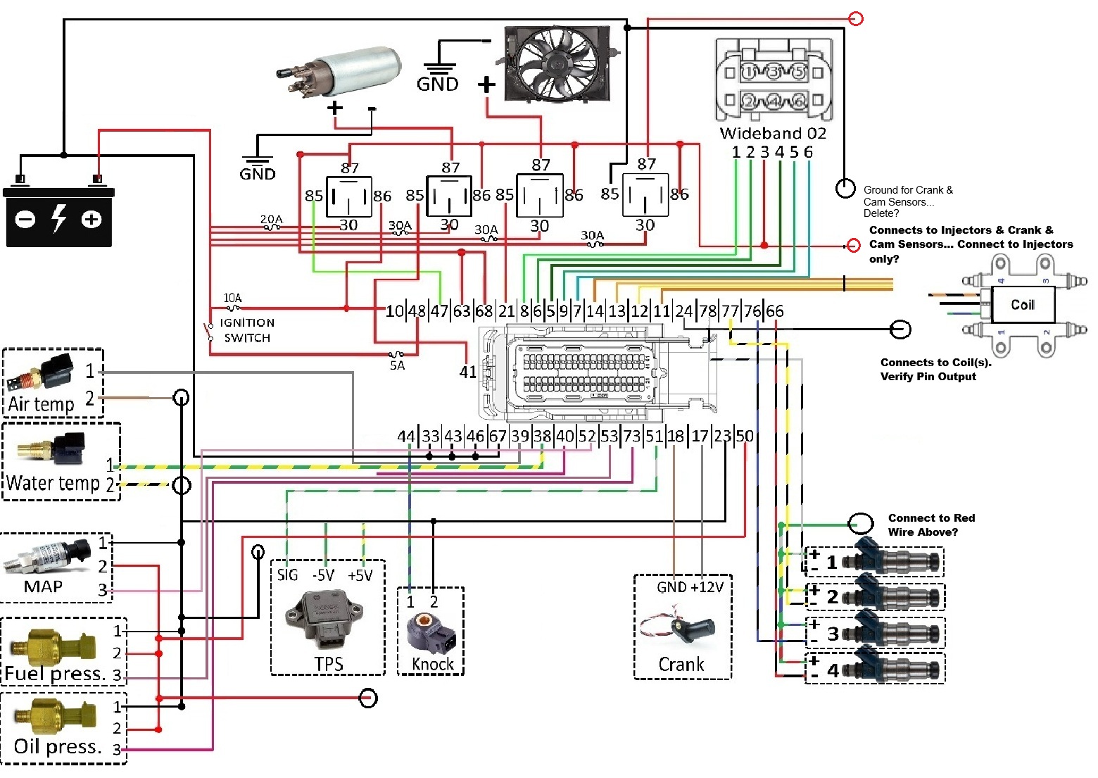
As of right now, this is how far I’ve made it with the wiring diagram. I was able to find a generic AEM wiring diagram with a 4cyl. Feel free to critique that as well.
Same reason why federal Esprits sat so damn high on their springs.
I am glad to read that I am not the only one who struggled with fitting the QED Crank Position Sensor bracket. There is not enough space for all the fingers you need to hold the bolts and washers and sleeves in place while securing. I ended up using some sacrificial masking tape over the bolt heads. If you haven’t fixed it all up yet, I recommend tack welding/brazing the sensor-securing nut onto the bracket. Unless secured, it will be a challenge to hold the nut in place when fitting the sensor. And probably impossible to do so on a dark roadside if you ever needed to replace a fan belt.
Thanks Damian… I wish I wasn’t struggling with this entire conversion. Hindsight being 20-20 I wish I had sprung for the full QED from the beginning and “upgraded” to the heritage ITBs later… but now that I’ve relentlessly begged them to sell me an ECU and harness to no avail Im stuck crawling at a snails pace towards having a somewhat completed harness. I’m really out of my element and worry my frustration might get the better of me… I’ve owned this car for 6 months only to have driven it approx 3 miles when it was presented as a good runner on the Webers. My irritation with tuners got me here (another poor judgement error on my side) so I feel I’ve given myself 2 strikes and am worried what will happen if I commit a third…
/rant
I decided that the best thing to do was to actually call QED instead of sending my whiny emails. And wouldn’t you know it, Simon answered the call and confirmed he had seen my emails, but just that he was behind. I explained my current situation, that I was basically willing to purchase a kit sans ITBs and Crankfire kit as those were two items they sell individually and major items I’m currently in possession of… The AEM ECU and related sensors can be placed to the side for another project down the road.
I’m hoping this wont be too painful financially as I believe I will have to pay an additional 20% on Trumps Tariffs to punish … the UK?… by making ME pay more??… regardless, this whole project has been one mistake after another, hopefully this will be a reset towards the right path. Hopefully I will at least have it soon.
Was on my way to work and figured I should give QED a ring and see how he was coming along. I was worried they wouldnt answer, but after a few rings he picked up. I asked for an update on my order and he said “hand on heart, I totally forgot” and while this was a little frustrating, I fully appreciate honesty. He asked me to send him an email on a different email VS the regular ‘sales’ or ‘info’ inbox so hopefully I have something ready to ship out to me soon.
In the meantime, I’m trying to keep my motivation on this (daily struggle) so I posited a question in the other thread I started for general EFI Conversion discussion. Its about the o2 sensor and my curiosity about where its welded onto the Elan exhaust. If you have an answer, I ask to reply in that thread so that others can use that info down the road.
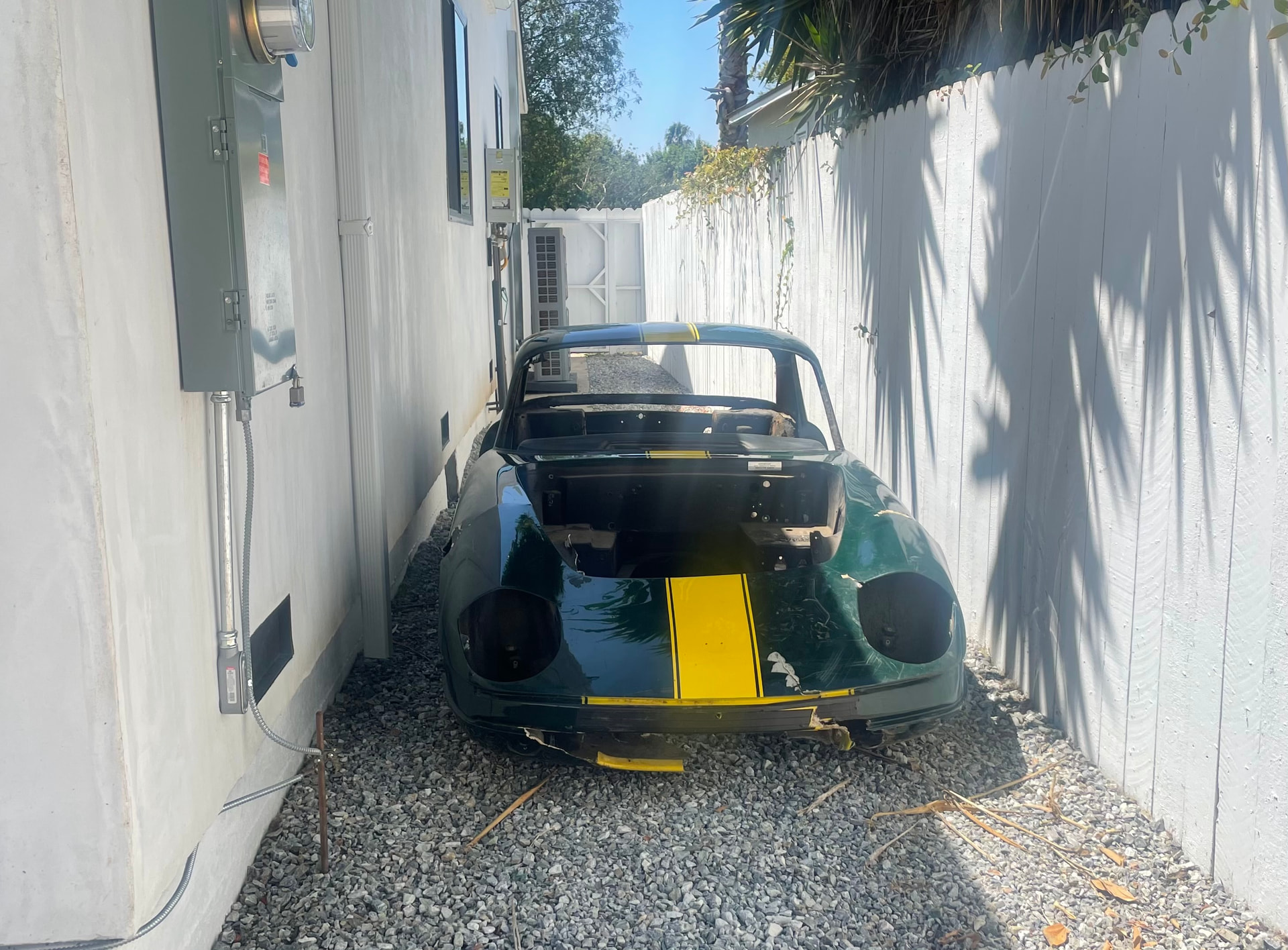
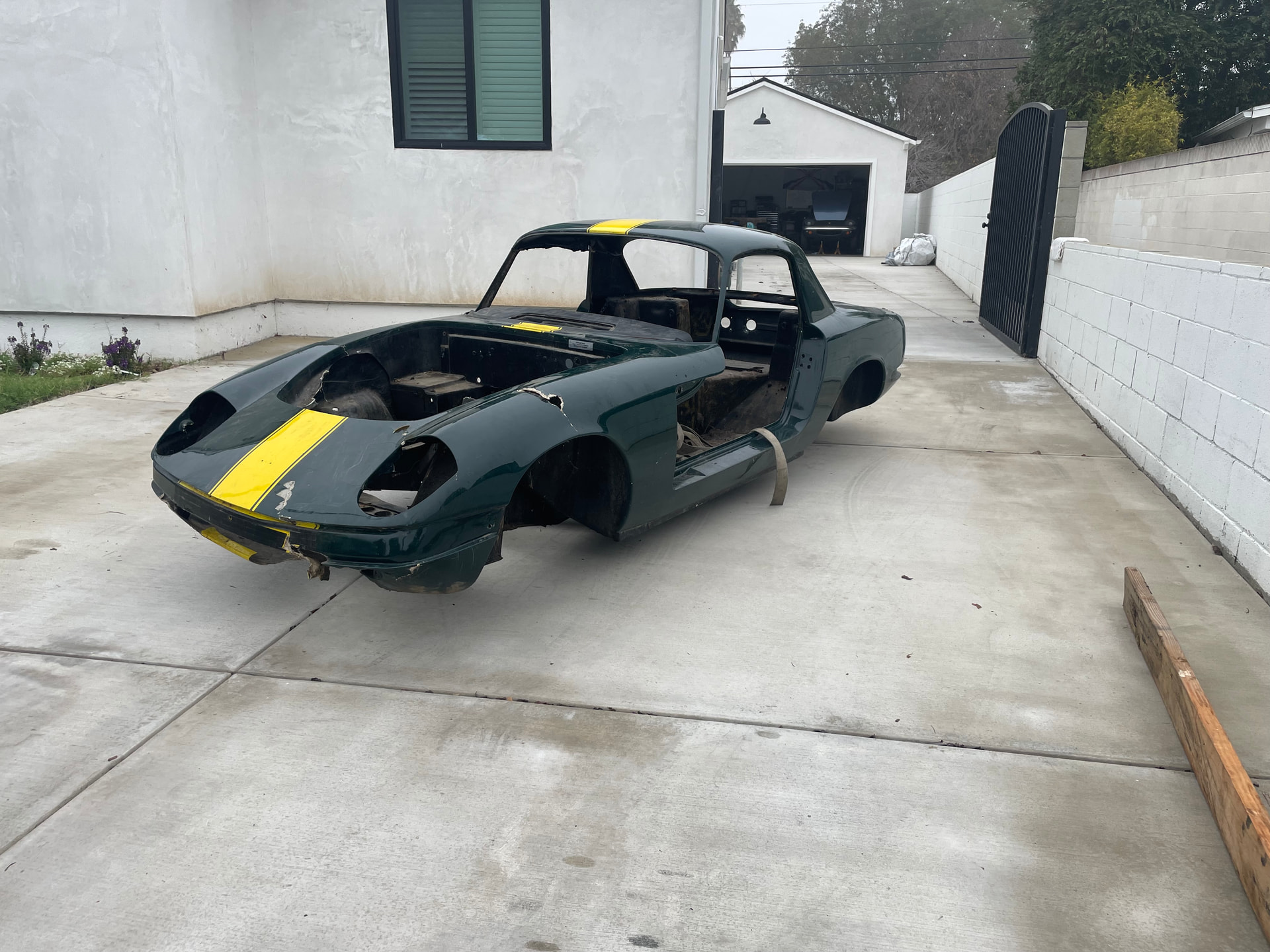
Well, one thing I needed to help move this project along was selling the previous Elan project.
Luckily I met a guy locally who has a Cosworth motor from a Formula car that he is going to detune it and toss it into the chassis… I wish him well on his journey while Im stuck on mine… the Elise has been calling me, but I’m not answering because I want and need to see this project all the way through and experience the Elan in all of its glory.
Adios friend
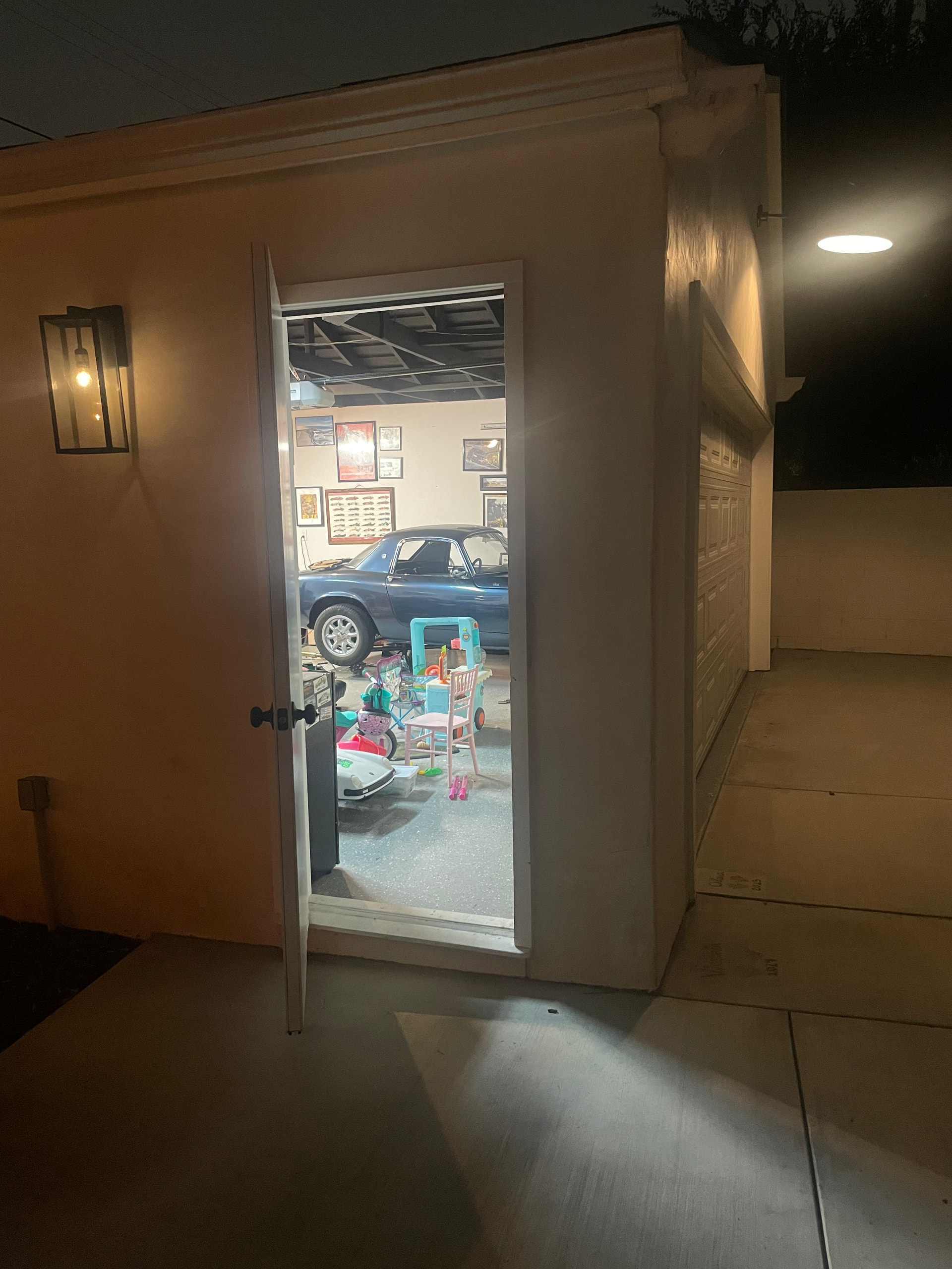
Got my one allocated night in the garage last night and wanted to work on a few other non-engine wiring related tasks. (I liked this for some reason so snapped a pic)
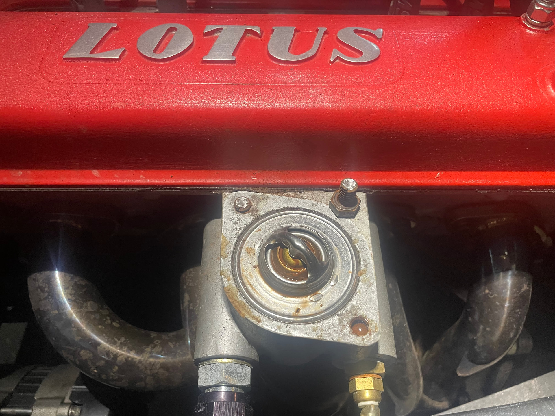
Step1 was to simply remove the thermostat housing to prep for a cool little piece that a member here had made for me. Easy enough, right?…
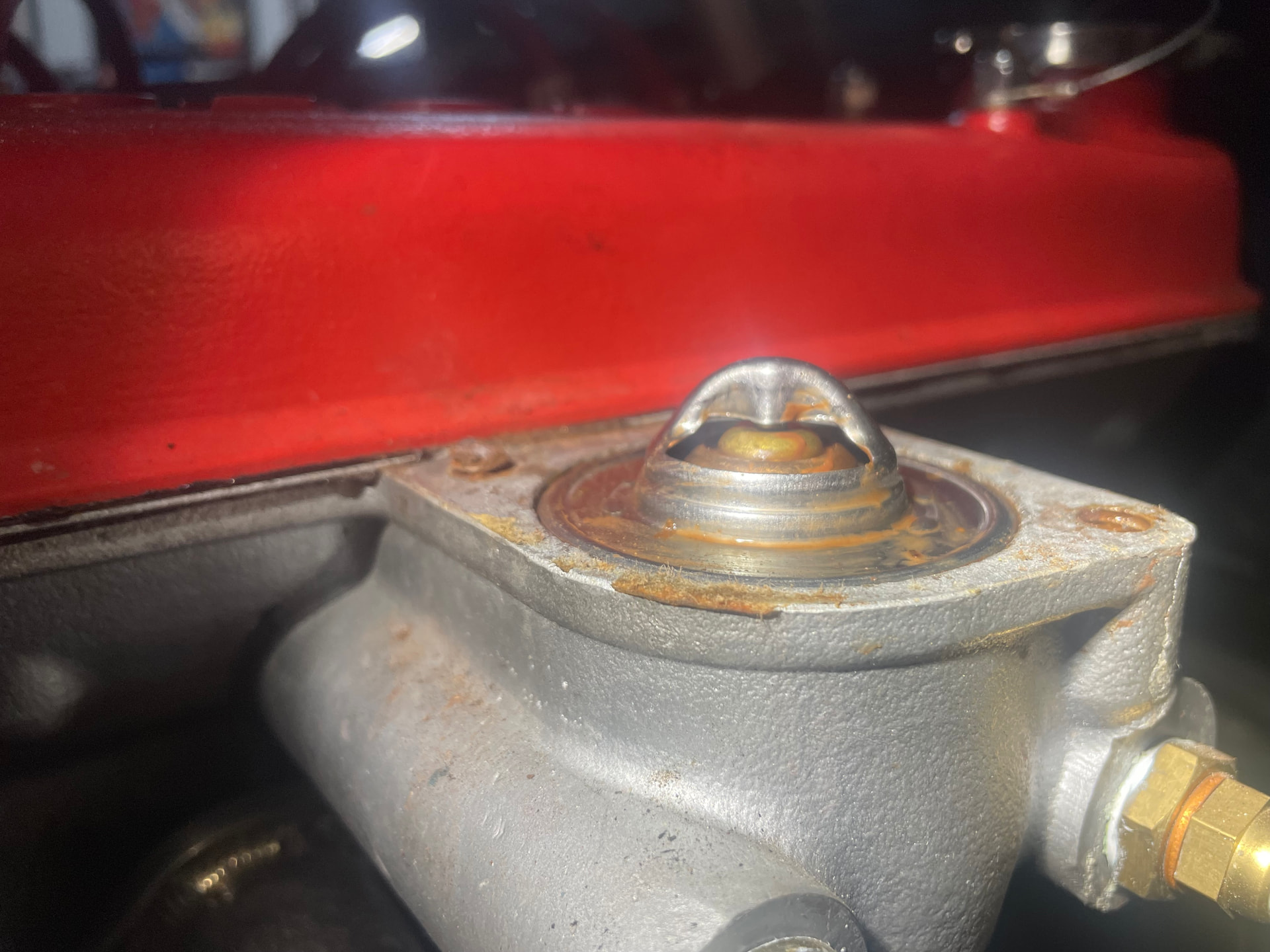
well that sucks… I have about 2mm of stud sticking out, so I’m going to try a combo of cutting a slit for a flat head and hoping with some heat it will cooperate.
I have terrible luck with easy outs so I’m hoping to avoid drilling anything… we’ll see..
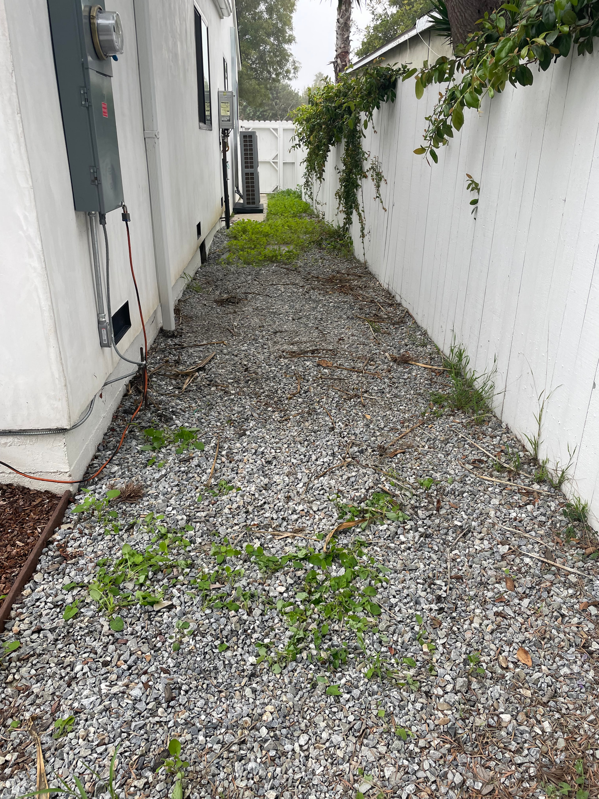
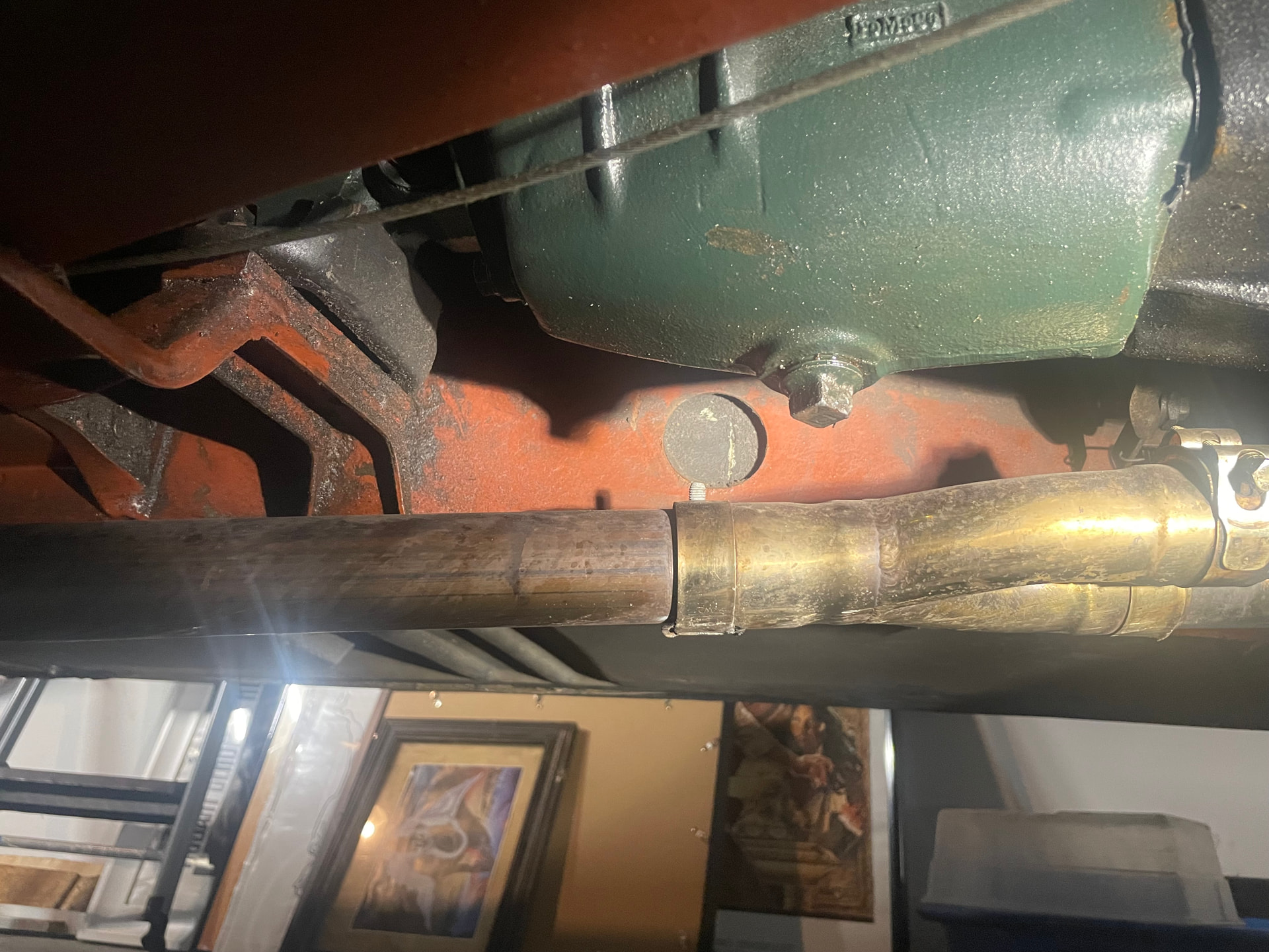
With task 1 turning into a nightmare I shifted my attention to #2 which was to remove the exhaust section that I plan to have my wideband sensor bung welded, and this spot seems the best, but not sure exactly where to run the wiring up into the car from.
That hole in the frame seems tempting but I think I’d have to drill into fiberglass to get it into the cabin and that’s another drilling situation Im trying to avoid.
W heading out of town for the achritmas holiday next Sunday so this upcoming Saturday night Im hoping to have that stud extracted and who knows what else… taking suggestions on stuff I can work on while waiting for QED…
I am probably way out of my depth here, but should there not be a missing tooth on the crank sensor, or does it get positioning from a cam sensor? I have both but the crank sensor has a missing tooth.
The good news is that access to the problem is perfect. Personally I do not think that cutting a slot and then using a flathead screwdriver will work as the stud must be pretty tight / coroded in there to break the bolt.
I would remove the stat and drain the coolant down. Then drill a small hole, say 2mm drill size, about 2mm down into the stud on the very edge of the stud closest to the stat. Then soak the stud and area in penetrating oil for 24hrs, keeping it wet. Then heat the head up with a fine blow torch around the stud to quite hot. Then, with a quality punch placed in the hole you drilled, whack the punch, facing in an anti clockwise direction. If you can get the stud to move a fraction, you have won, it will turn out.
If that fails, it would be a simple task to drill the stud out using successively larger quality drills. The trick would be starting the first drill as centrally as possible.
I have used the first method and it worked, but not on an ali head. A stud had broken off in cast iron.
Good luck with it.
Leslie
Regarding Leslie’s second method another tip is to use drill bits that cut anti-clockwise i.e. you also have to run the drill in reverse. I didn’t believe it would work (and I didn’t know they even existed) until an old pro actually showed me one day. We had to finish using an Easy Out extractor, but the anti-clockwise action of the drill had seemed to loosen it. That was in an ali casting.
Mike
If you are using left handed drills, use cobalt drills, lubricant/coolant and low speeds.
I have used these extractors for both my Elan and my Formula Ford. They drill left handed, then remove the bit and thread the screw in the drilled hole, again left handed. https://www.homedepot.com/p/Milwaukee-M2-Steel-Screw-Extractor-Set-4-Piece-49-57-9001/325254980
Another method is to weld a nut to the top of the broken stud, then back it out before it cools. Lots of videos on how to do that on Youtube.
Having thought about the job over night, I do not think my first method will work. If the bolt was the correct length, there will be about 3/4” left in the head, and I do not now think that tapping the bolt anti clockwise will move it in ali, and drilling will be the only way to remove it.
I doubt that the welded nut would work in this application either, but who knows.
I would file a flat on top of the stud and centre punch the centre, then get drilling. Imperative that you go in vertical.
Leslie
That bolt is not in a blind hole but is going through the thermostat housing, the bolt tip dips in the cooling water so to speak. In mine at least. If you are going to drill make sure to put some cloth or so inside the housing to catch chips and debris.
One more vote for left-hand anti-clockwise approach. Another favorite of mine in this kind of situation is freezing rather than heating. CRC makes a freeze spray that I have had some luck using. Drill the hole first, then spray into it. It will shrink the bolt and help break the bond.